
Eldar Pegasus
scratchbuilt superheavy grav tank
The Eldar Pegasus is a scratchbuilt superheavy transport. Its design was originally inspired by a tiny image of a vehicle from a piece of artwork of the Lugganath craftworld, first published in the 5th edition Warhammer 40,000 rulebook. The name was chosen based on a reference on page 37 of the 4th edition Eldar codex to a "winged steed" ridden by the Eldar god Asuryan. The project was completed on 21st February 2020; 9 years, 1 month and 12 days after I first started tinkering with some spare Falcon pieces in my bitz box. It was featured in issue #459 of White Dwarf, fulfilling a lifelong ambition of mine in the process.Date: 2011 - 2020 (complete)
Components: 3x Eldar Falcon kits, 1x Wave Serpent rear hatch frame, 1x Forge World Type II Falcon conversion kit, 1x Forge World Phantom Titan D-cannon, 1x Forge World Phantom Titan torso, 1x Forge World Firestorm targeter, 66x custom laser-cut anti-grav vanes (2mm acrylic), 1x metal Fire Prism sensor, 1x plastic Fire Prism rear hatch, 1x Crimson Hunter Pulse Laser, 1x Crimson Hunter Bright Lance, 1x Crimson Hunter Starcannon, 1x Wraithknight Scatter Laser, 1x Wraithknight Shuriken Cannon, 1x transparent flying stand, 1x Forge World Eldar Hornet pilot, 1x Webway Gate, plasticard (various thicknesses), Green Stuff, White Milliput, styrene tubing (various diameters), neodymium rare earth magnets (various sizes), brass rod, 320mm round MDF base, Polyfilla, cork floor tiles
Colour scheme: Craftworld Miruaun colour scheme (PDF), Basing colour scheme (PDF)
Related:
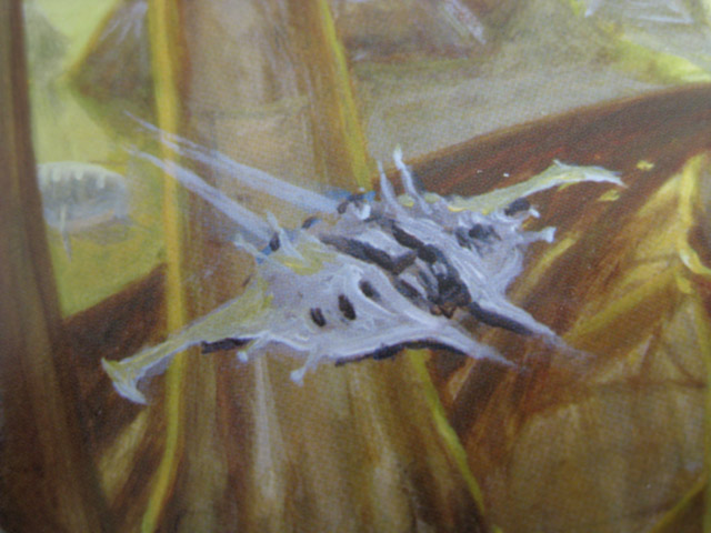
1. This is a close-up of the artwork that inspired this project. Though it is not particularly detailed, the (unnamed) vehicle has some distinctive features, namely the triple engine intakes and the low, wide profile. The design I came up with uses this as inspiration rather than trying to recreate it exactly.
Original image © Games Workshop.
Original image © Games Workshop.
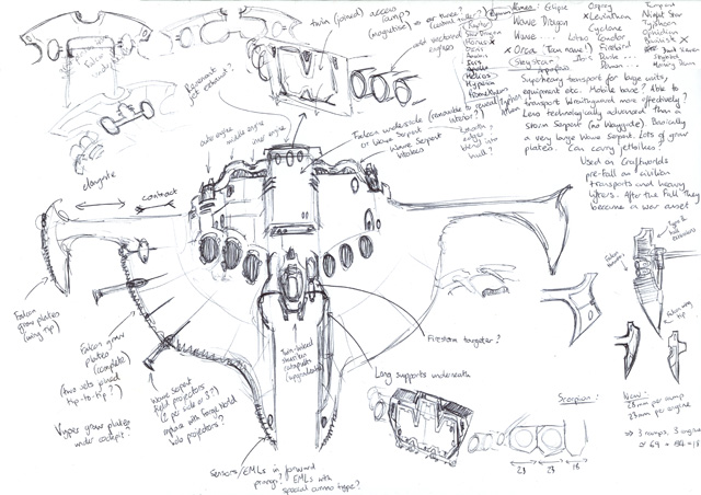
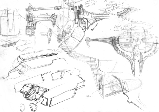
2. My first rough concepts and notes (the proportions in the sketch are very, very wrong!). I originally based the design around a double-width access ramp, however I quickly realised that in order to carry signficantly more units than a Wave Serpent, the Pegasus would need a much larger troop compartment and, correspondingly, a larger access ramp. The ramp on the Pegasus ended up three times the width of a standard Falcon ramp.
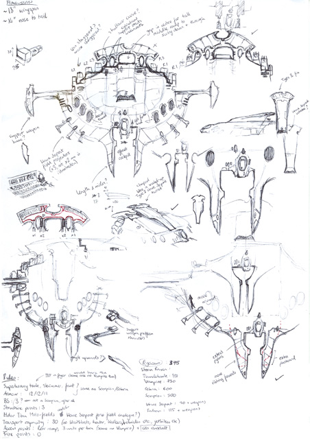
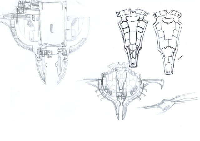
3. More detailed design concepts and sketches. I incorporated a large fin at the rear of the vehicle, mimicking those found on the "Type II" vehicles of the Forge World Eldar range. All of my other grav tanks have these Type II hull extensions.
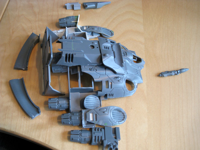
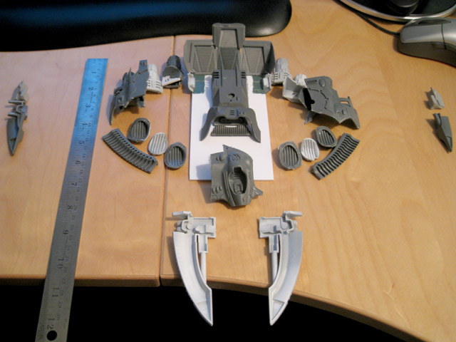
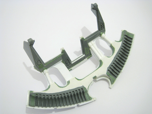
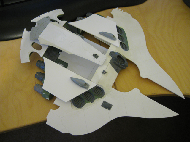
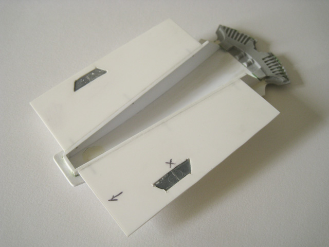
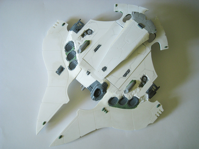
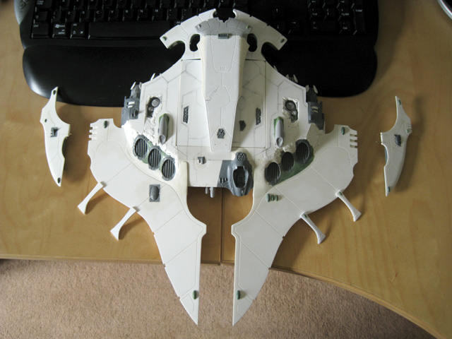
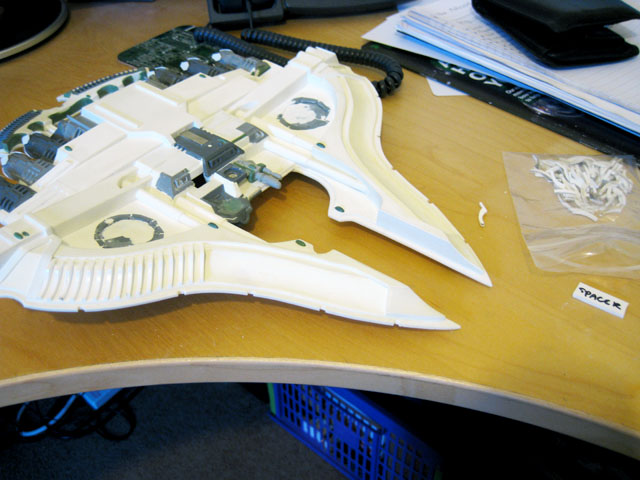
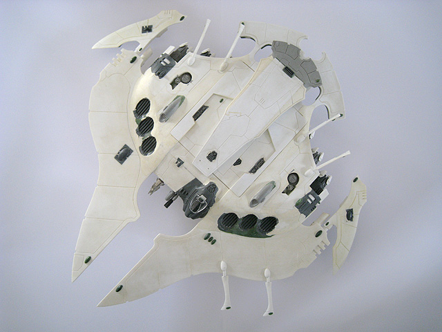
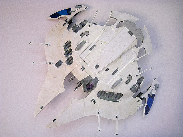
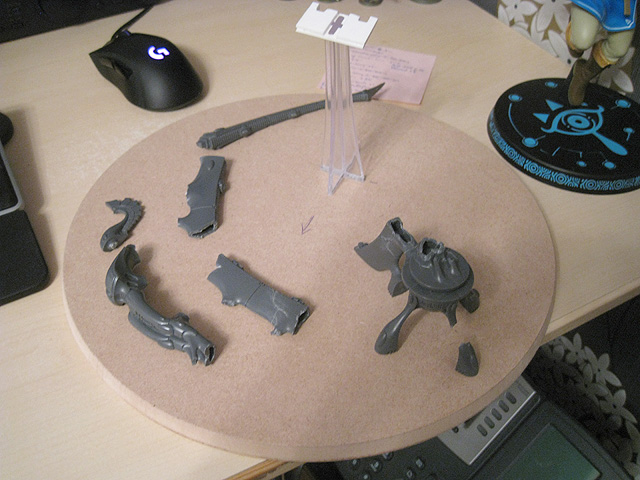
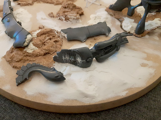
4. When dealing with a conversion of this scale, I find it helpful to lay out the various components to get an idea of the rough shape and size. It's also useful for experimenting with different combinations of bits.
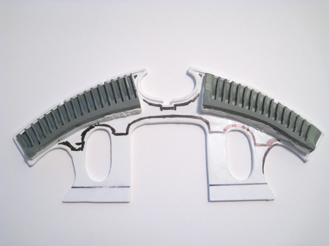
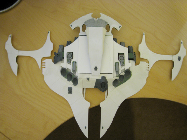
5. A later, more developed layout of the pieces, once I'd started work on some of the individual components.
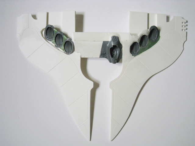
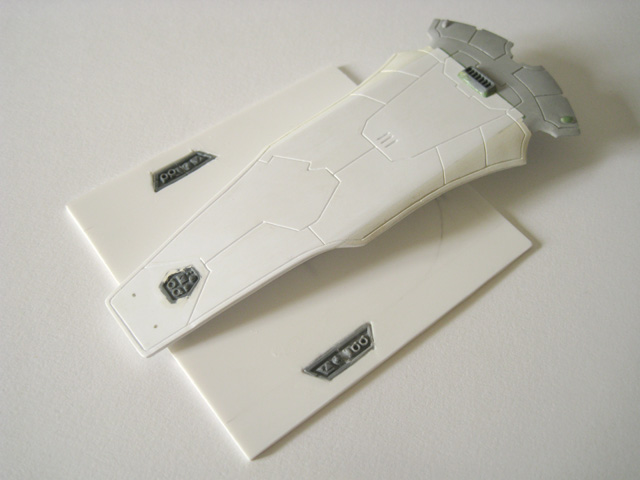
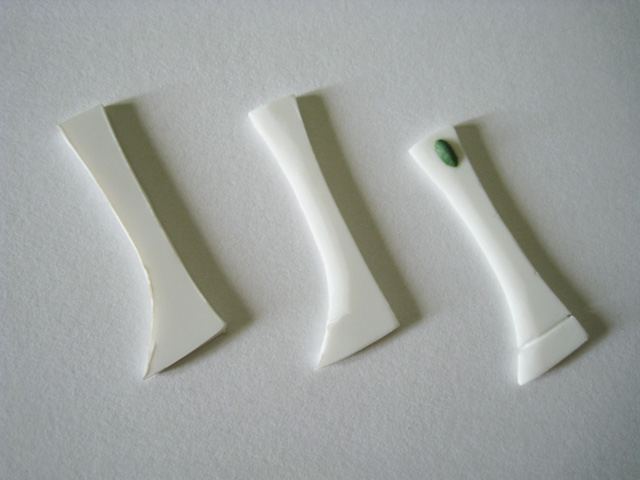
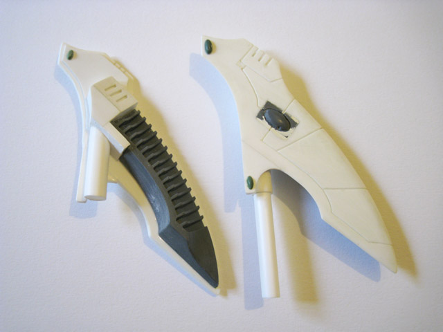
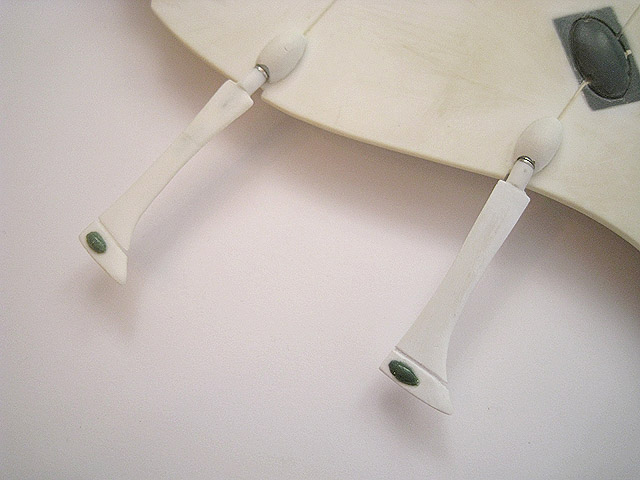
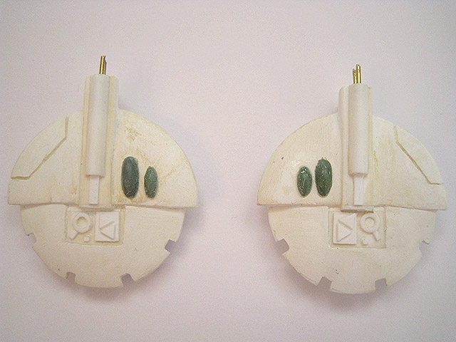
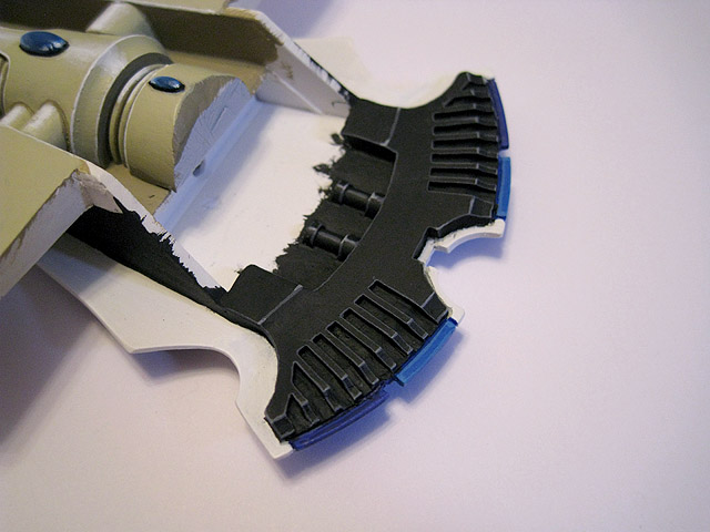
Some of the raised gems were removed from each of the identical ramps to avoid repetition and make the completed, larger ramp seem more cohesive.
Green Stuff was used to fill in some of the recessed details and blend the ramps together.
The ramp hinges were carefully pinned and glued together.
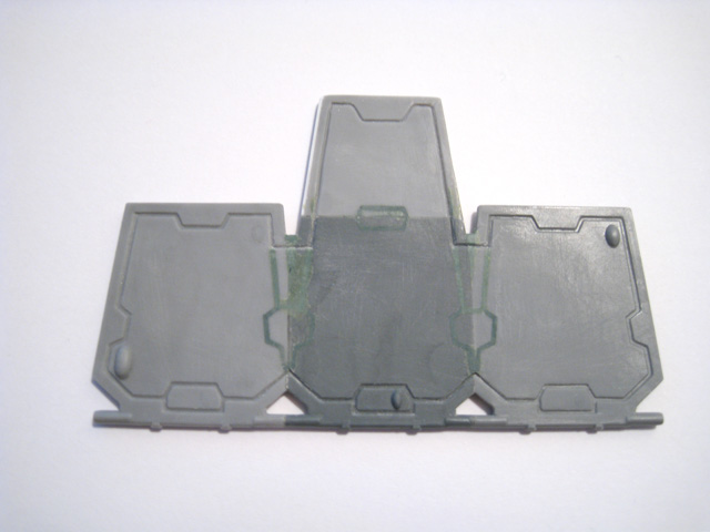
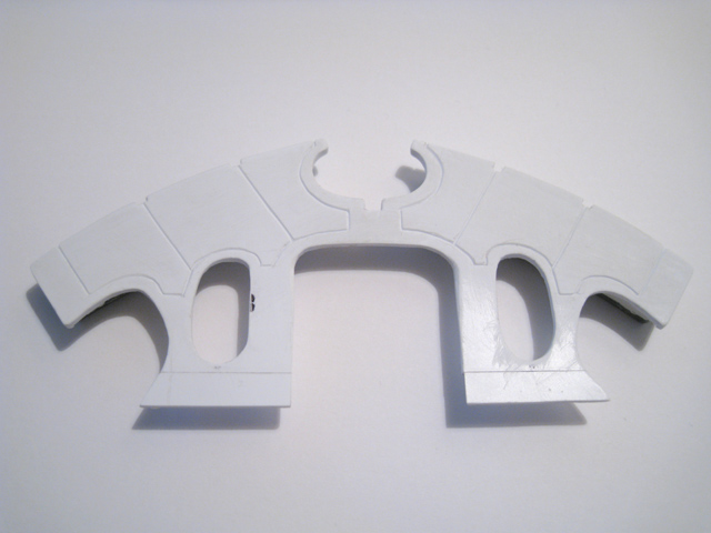
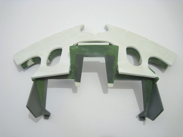
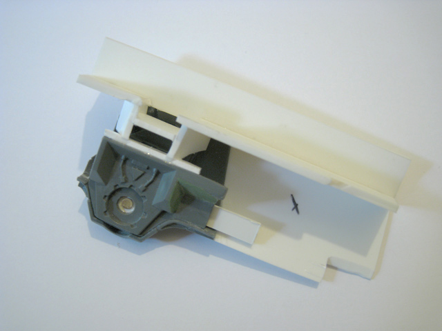
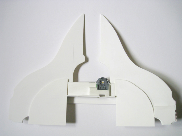
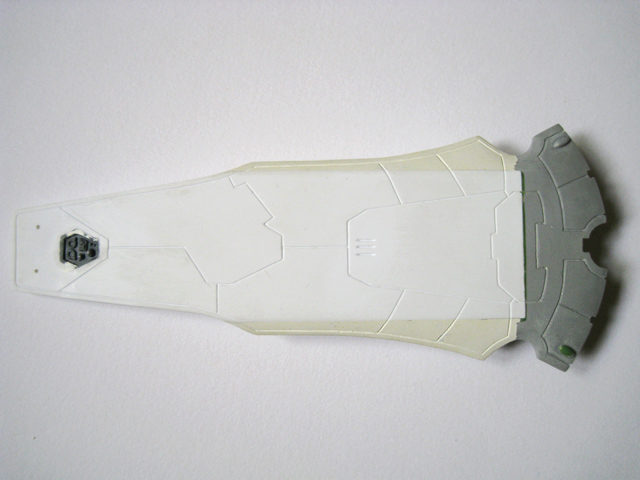
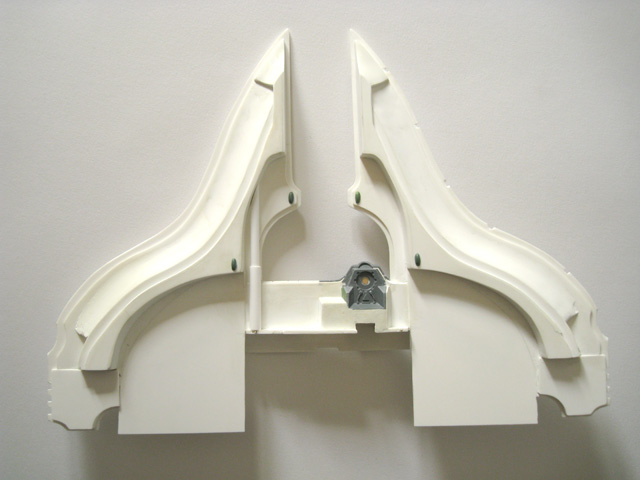
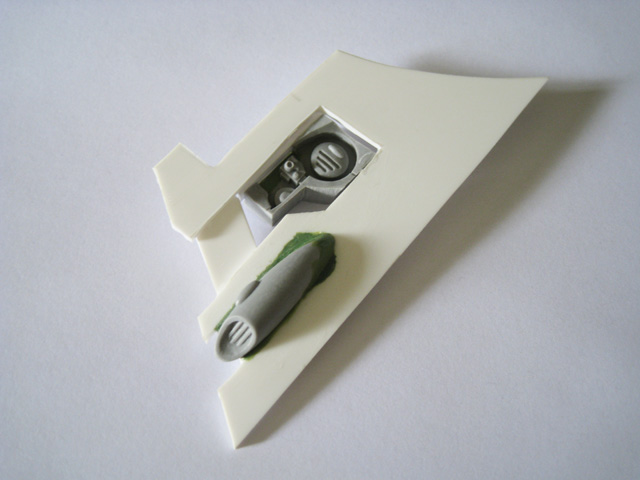
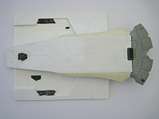
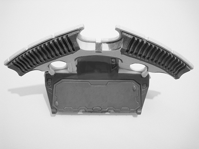
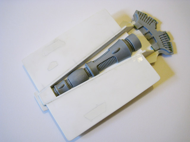
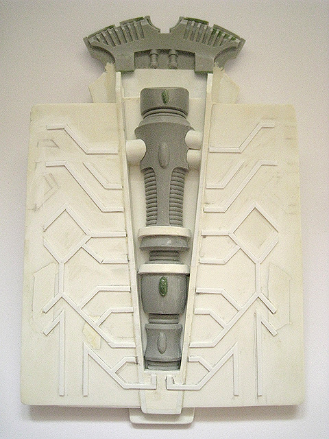
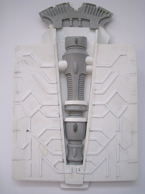
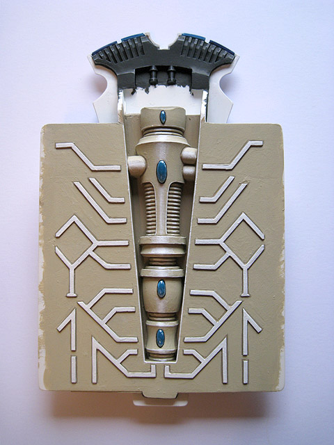
6. The rear access ramp was the first component of the conversion that I assembled, though it was later revised and the central protrusion removed. I decided from the outset that the Pegasus would have a fully-detailed interior, with a magnetised access ramp.
This triple frame was made by pinning the smaller doorframes from two Falcons and one Wave Serpent kit together.
The central frame was cut down to make it narrower.
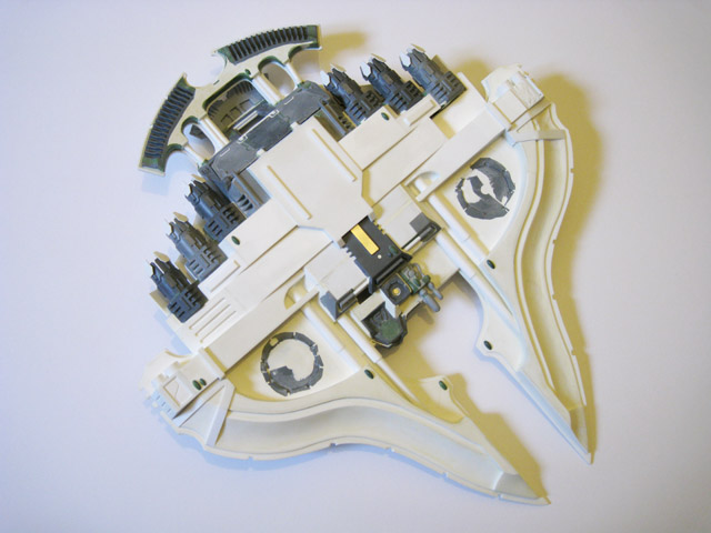
Each bit of detailing on the hull was changed in some way to avoid obvious repetition of the same designs.
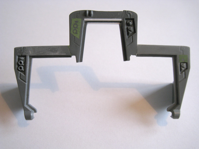
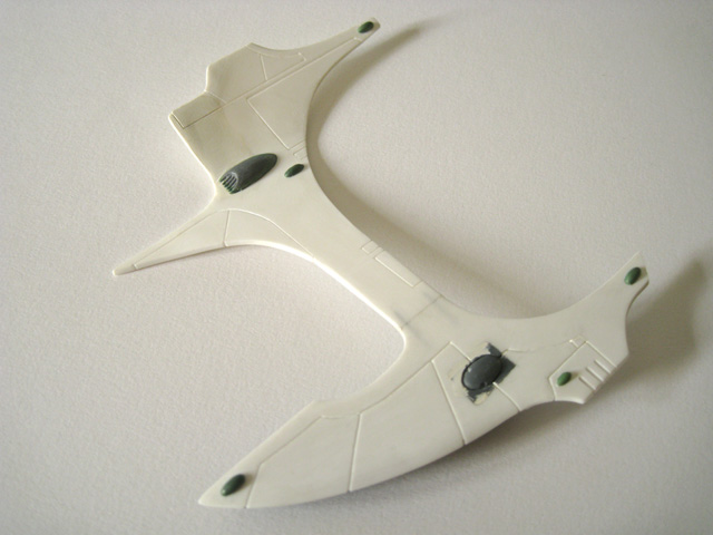
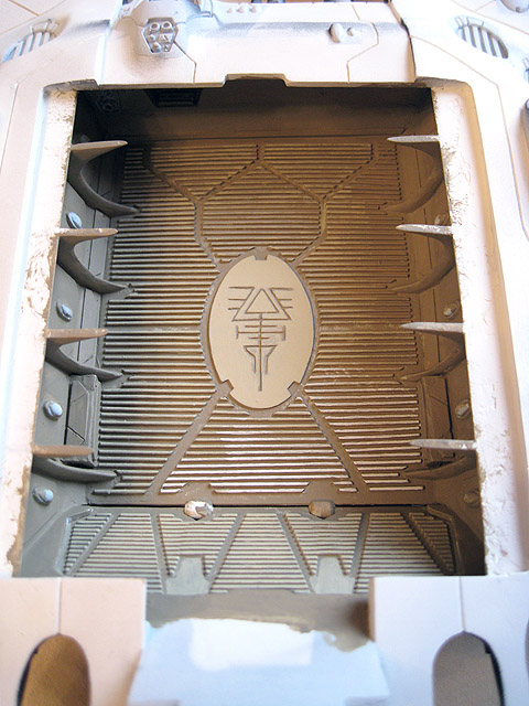
7. The rear access ramp and the surrounding frame were the first parts that I worked on, since their size and shape would inform decisions about much of the rest of the vehicle's layout.
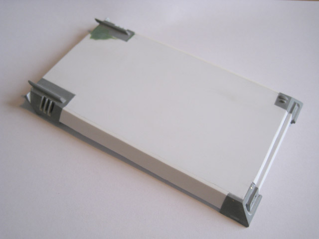
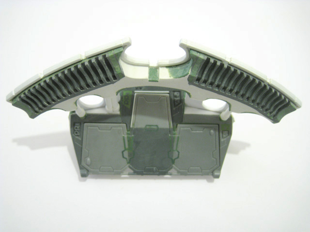
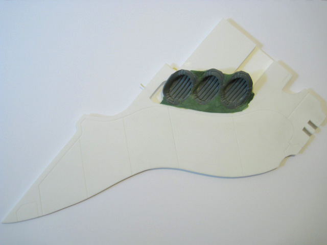
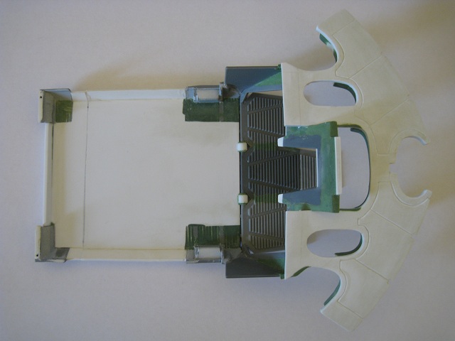
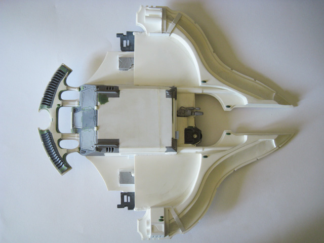
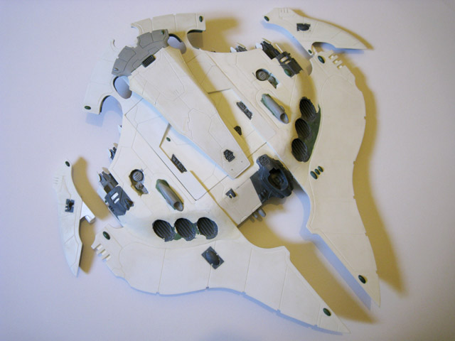
8. Once the rear of the hull had begun to take shape, I put together the base. This is a ventral view - the reverse side forms the floor of the troop compartment. This section would later be reduced in size.
The tracks in the hull were scored into the plasticard using the point of a needle file.
These oval-shaped holes echo the design of the fin on Forge World's Type II Scorpion model.
This gap in the centre was originally included to allow the taller middle section of the ramp to swing open unobstructed.
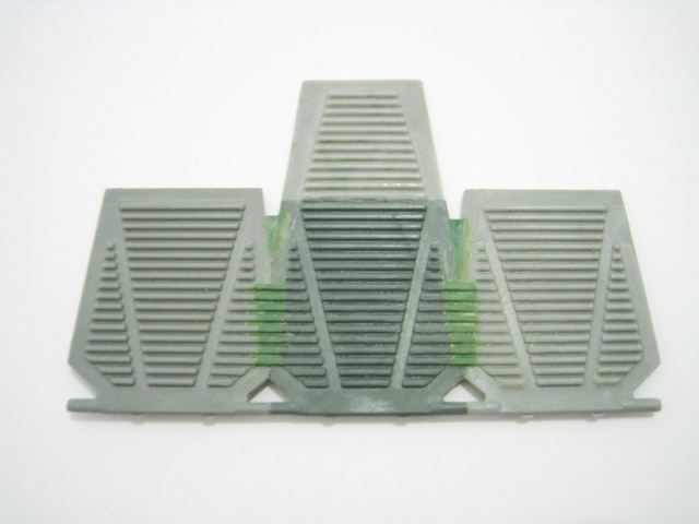
9. Next I started working on the large "Type II"-style rear fin, cut from a single piece of 2mm-thick plasticard. My approach with this project was to build individual components to be glued together later; like building the pieces for a kit in effect. Each piece informed the shape and size of the next piece, eventually producing a coherent result whilst still allowing lots of dry-fitting and room for correcting mistakes.
10. The underside of the rear fin. The design quite closely mimics that of the fin on the Scorpion.
11. Further design sketches. At this stage the proportions and details of the Pegasus were becoming more defined.
This raised section was mostly created using white Milliput, with some Green Stuff for the smooth curved surfaces.
These connecting pylons were made using different diameters of styrene tubing.
12. The underside of the rear fin, after it was attached to the rear frame.
13. A topside view of the rear fin and frame.
14. The rear of the Pegasus begins to take shape.
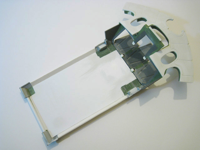
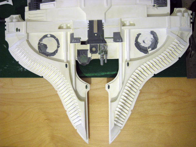
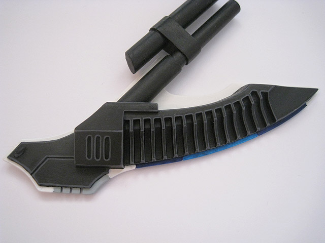
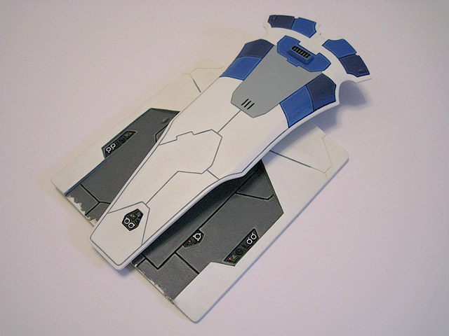
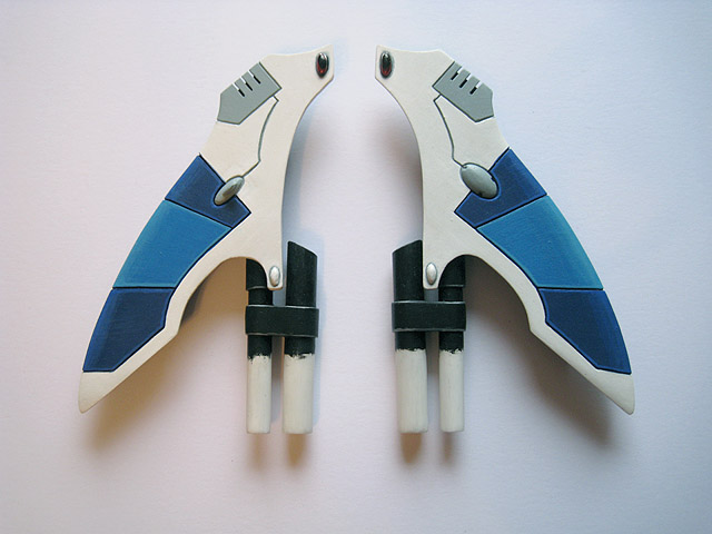
15. The over-sized access ramp.
Each engine block was made using a Falcon engine, bulked out with thick plasticard, white Milliput and Green Stuff.
The engines have been pinned together using brass rod for added strength.
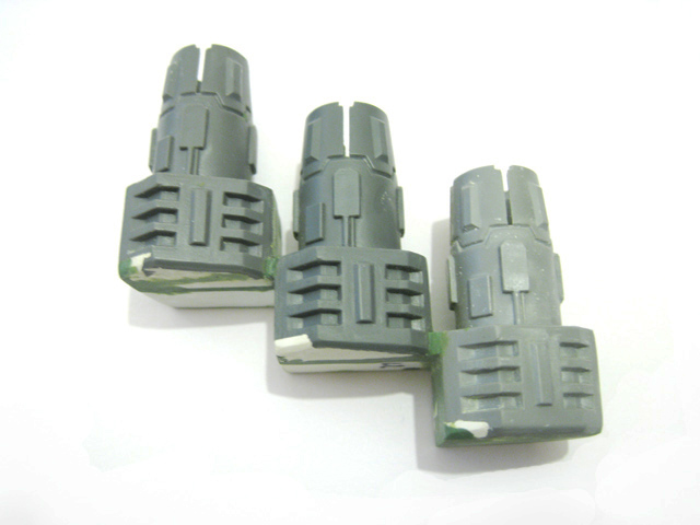
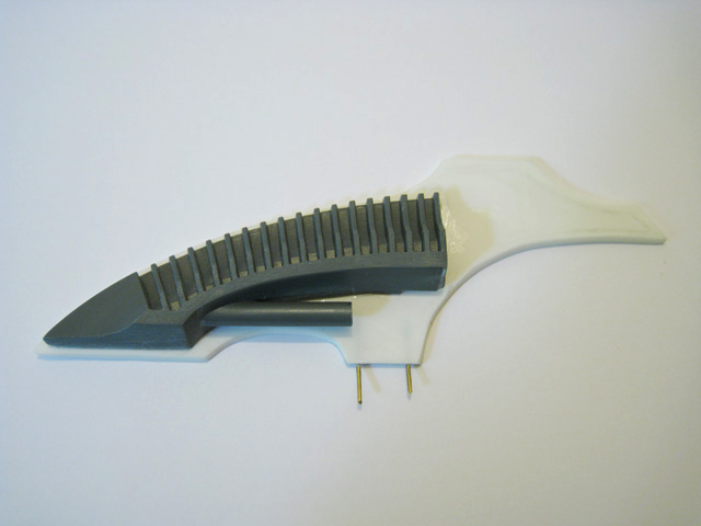
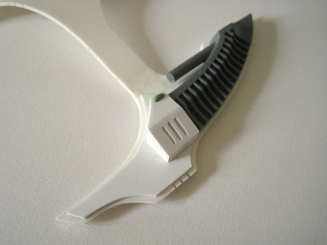
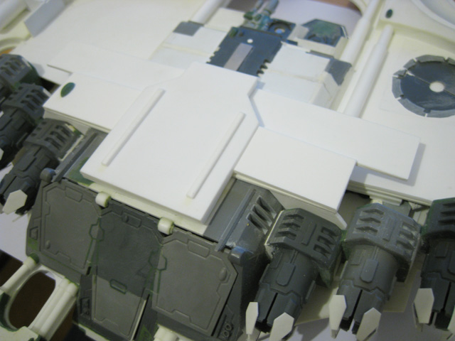
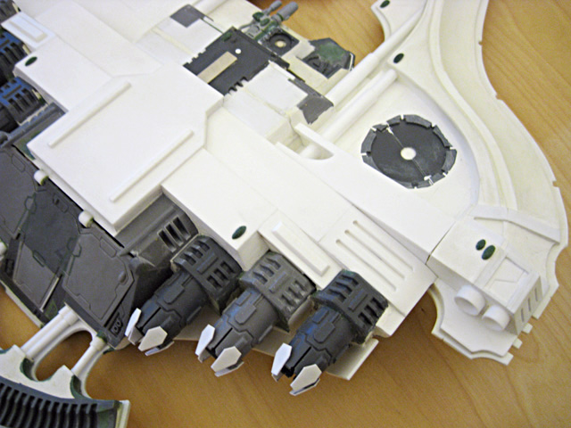
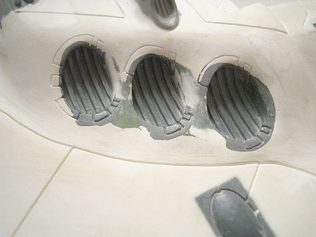
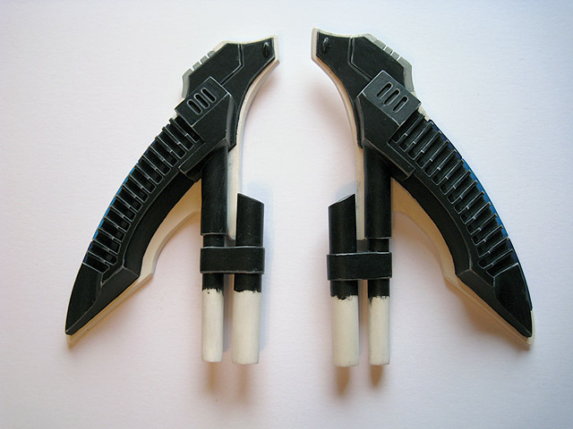
16. The starboard-side triple engine cluster.
This smaller fin was taken from a Forge World Type II Falcon conversion kit.
These sloping fins were made using plasticard, with white Milliput used to create a smooth, curved join with the flat topside.
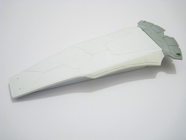
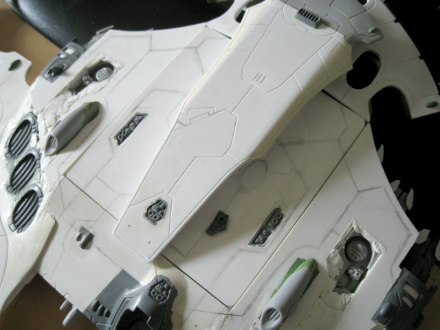
17. This piece is part of the upper hull. The shape is meant to appear similar to the Type II Wave Serpent turret (albeit much larger).
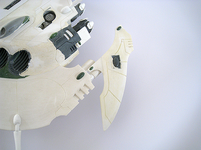
18. One of the wing tips.
19. The underside of the port side wing tip.
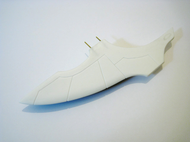
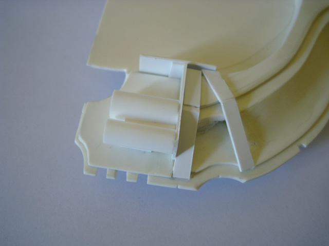
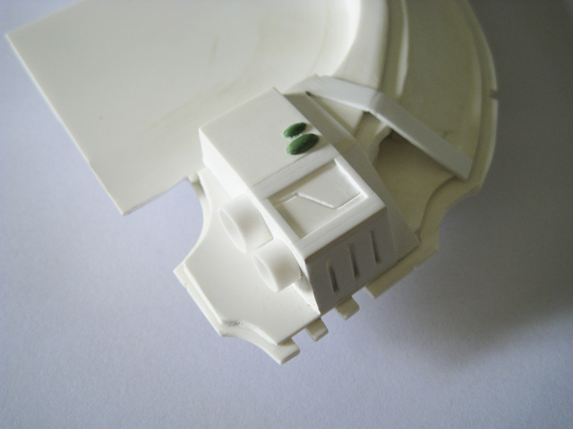
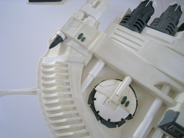
20. The cockpit begins to take shape.
21. The underside of the cockpit, showing some of the plasticard internal construction.
The wing is made from a single piece of 2mm-thick plasticard.
Each air intake was taken from a Falcon kit, cut down and then blended into the plasticard wing using Green Stuff.
22. The port side main wing.
23. The body of the Pegasus starts to come together as the rear hull is joined to the floor of the troop compartment. At this point, it is already as long as an entire Wave Serpent.
24. Some more design sketches of various aspects of the Pegasus.

25. At this point I started tracing existing parts of the Pegasus to create 1:1 scale sketches for new components. This was the original design for the wings - once I'd cut out a template, I shortened the wingspan slightly to keep the Pegasus well-proportioned. Eventually the wings were scrapped entirely in favour of smaller fins.
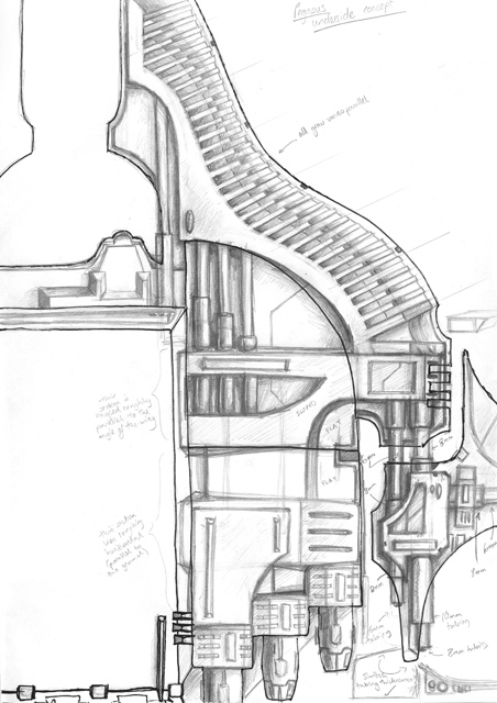
26. A detailed, 1:1 scale concept sketch of the underside of the Pegasus. At this point it became apparent that the unusual, undulating edge of the forward prongs would mean that I'd have to make custom anti-grav vanes, since I wouldn't be able to re-purpose those from the Falcon kits.
Styrene "I-beams" provide structural rigidity and also ensure that the upper and lower layers of plasticard are equidistant.
This area will be filled with Milliput, shaped to make a curved sloping surface.
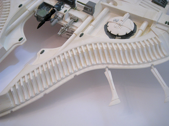
27. The anti-grav vanes for one of the forward prongs begin to take shape.
28. The forward hull continues to be assembled. This section of the Pegasus alone is as wide as a Type II Scorpion is long.
29. The underside of the forward hull.
This section of detailing was taken from behind the cockpit of one of the Falcon kits and recessed into the plasticard.
These vents were made using the same method as I use to make the panel lines (etching with the point of a needle file)
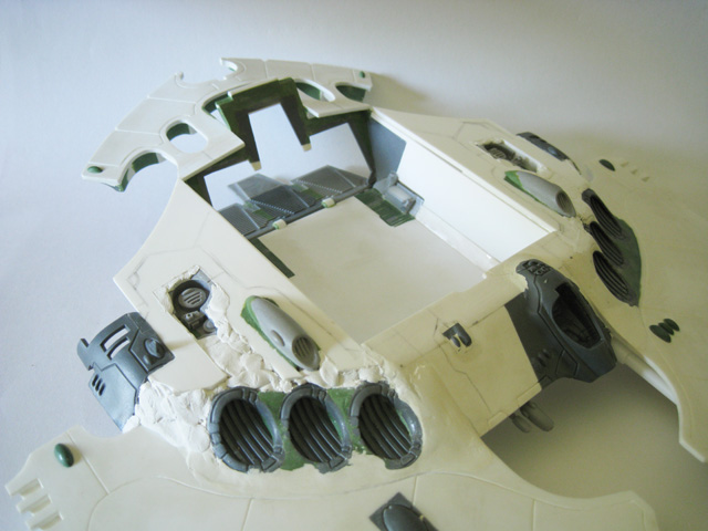
30. An updated shot of this section of the upper hull.
31. I decided that the troop compartment was too big, so I reduced its size significantly. Despite this, the footprint is still over 8 times larger than that of the interior of a Falcon.
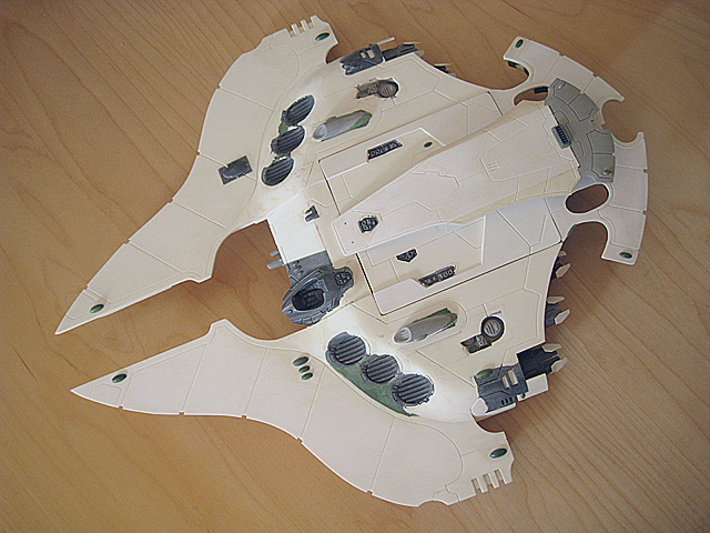
32. A mock-up of the Pegasus. The reduction in size of the troop compartment improved the proportions greatly.
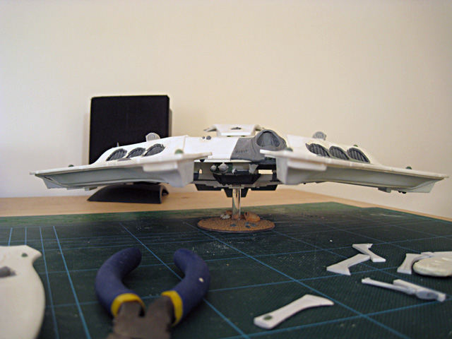
33. Another, more complete mock-up of the Pegasus. At this point the wings pylons were shortened as I wasn't happy with the proportions.
34. The upper hull takes shape. This will remain removable for much of the project to allow the interior to be painted, until it will eventually be glued in place and blended properly into the rest of the vehicle.
35. The underside of the upper hull.
This vent was taken from the hull of one of the Falcon kits and extended using Green Stuff.
This area of detailing came from the upper hull of a Falcon.
36. The port wing.
37. The underside of the port wing tip takes shape.
38. The front half of the vehicle starts to come together. Thanks to a lot of pinning and building components separately, the construction is satisfyingly heavy and solid.
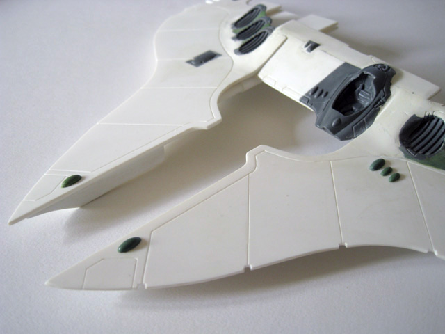
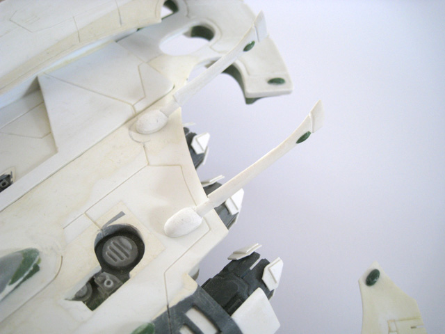
39. The front prongs of the Pegasus.
40. A shot showing some of the internal construction of the underside detailing.
41. A later image showing the same section after some work has been done on it.
42. Part of the upper hull, early on in construction. The resin parts came from a Phantom Titan D-cannon.
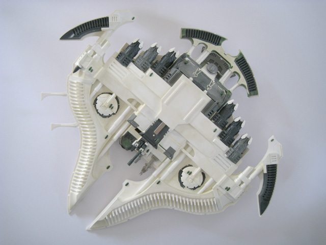
43. The Pegasus starts to come together, with most of the major components now glued together.
44. A shot of the work-in-progress interior with the upper hull removed.
45. The underside of the Pegasus.
46. Another work-in-progress mock-up. After much consideration, I decided to scrap the supporting pylons connecting the "pontoons" as the design wasn't working as well as I'd hoped. By bringing these "pontoons" closer to the main hull, I feel that the vehicle appears more cohesive and less ungainly than it did before.
47. Close-up showing the paths of the planned panel lines on the upper hull.
48. The detailing on this section of the upper hull was virtually complete at this point.
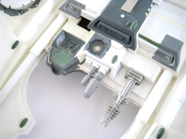
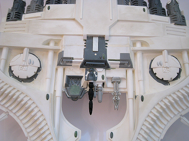
This sensor was converted from a Firestorm component.
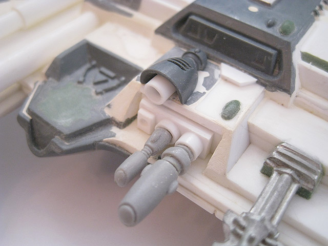
The weapon mount was positioned more-or-less centrally; had it been under the cockpit, the Scatter Laser would have been pointing at the forward prongs.
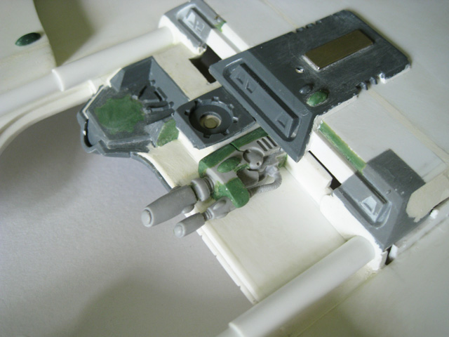
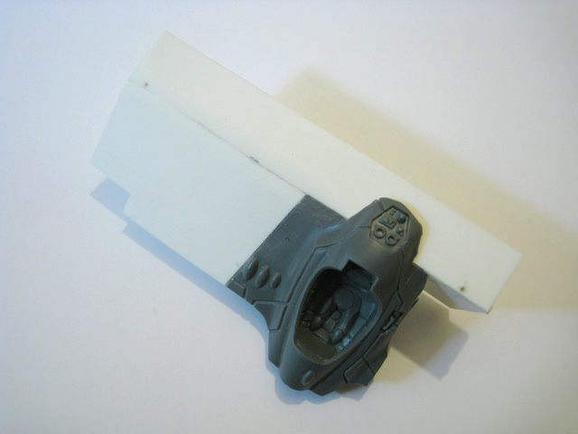
49. The underside of the cockpit, featuring advanced sensors and a weapon mount.
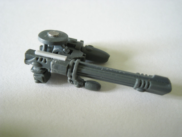
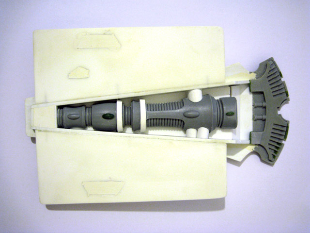
50. The weapon mount under the cockpit can accommodate the usual options of Twin-Linked Shuiken Catapults or a Shuriken Cannon. I also wanted the option to have a Scatter Laser; this was assembled using parts from the Shuriken Cannon from the Wave Serpent kit. This was eventually replaced in favour of a different style of weapon mount that could accept several different heavy weapon options.
51. These components will form the force-field projectors and are designed to look like scaled-up versions of those found on the Wave Serpent.
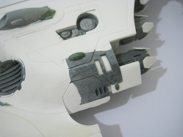
52. A close-up shot of the detailing around the port-side engine cluster.
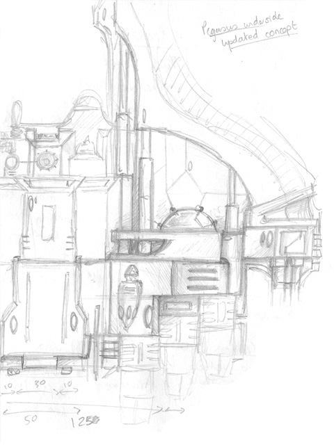
53. An updated concept sketch for the underside.
54. A work-in-progress shot of the underside. Most of the detail was constructed using different thicknesses of plasticard. The design takes some inspiration from the Scorpion.
55. An updated shot of the underside. The port side is virtually complete at this point.
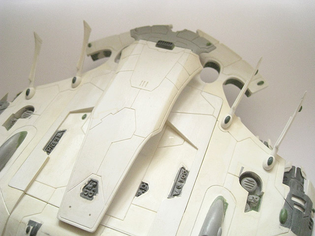
56. A dorsal view of the Pegasus, with most of the panel lines completed and only some minor detail work on the starboard side of the vehicle left needing attention.
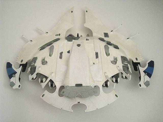
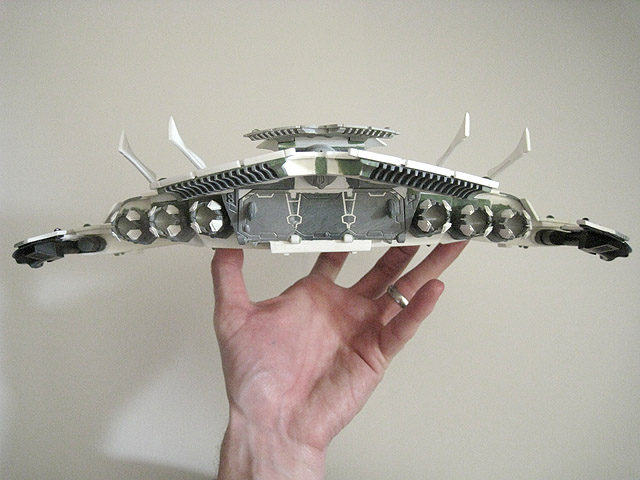
57. A shot of the Pegasus from the front, showing the low, wide profile.
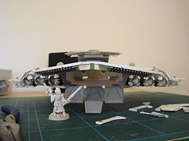
58. A rear view of the Pegasus, with a Warlock for scale. At this point the design of the ramp was queried and after some discussion on Warseer, I decided to change it.
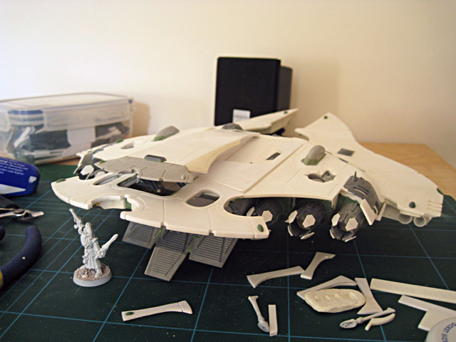
59. Another angle of the Pegasus illustrating the scale of the vehicle.
60. This Photoshop concept for the revised rear access ramp design proved the most popular among the Warseer posters - fortunately, it was my favourite one too!
This section will be filled in with plasticard.
The corners were cut down to make a more interesting shape.
61. The rear of the Pegasus, after the ramp shape was changed.
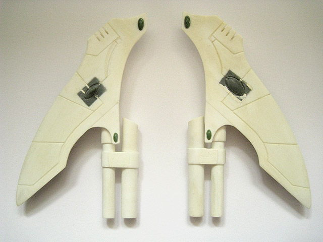
62. After much deliberation, the problametic and ungainly wings became fins, similar to those on the Type II Scorpion and Cobra (albeit larger).
63. The raised section of the upper hull now contains the generator necessary to power the Pegasus's shields and electromagentic pulse weapon.
64. An updated WIP shot of the underside, which is almost complete at this stage.
65. This picture shows the final positioning of the wings.
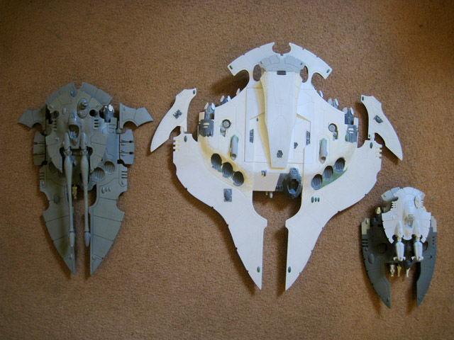
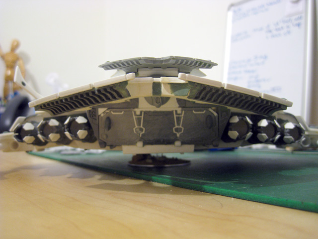
66. With the Pegasus's dimensions all but finalised, now seemed as good a time as any for a gratuitous size-comparison photo. The Pegasus is pictured with a Type II Scorpion and a Night Spinner. The Pegasus is 14" long, 15" wide, 3" tall and weighs around 620g. It's quite big.
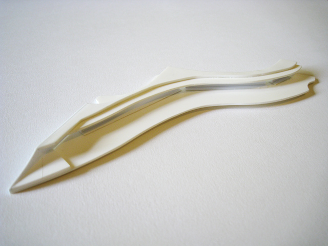
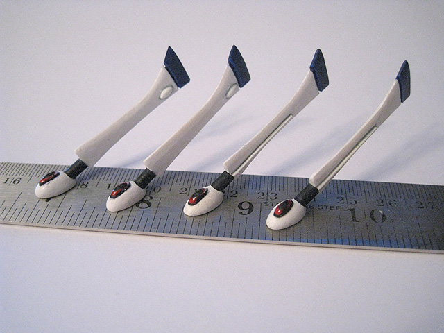
The original styrene master.
This 3mm-thick wedge of styrene was used to keep the vanes regularly spaced as they were glued in position.
67. Rather than try to cut 66 fiddly anti-grav vanes by hand, I created a single "master" from styrene that I then scanned and turned into vector artwork. This was then sent to Fenris Games, who used my design to laser-cut them from 2mm-thick acrylic.
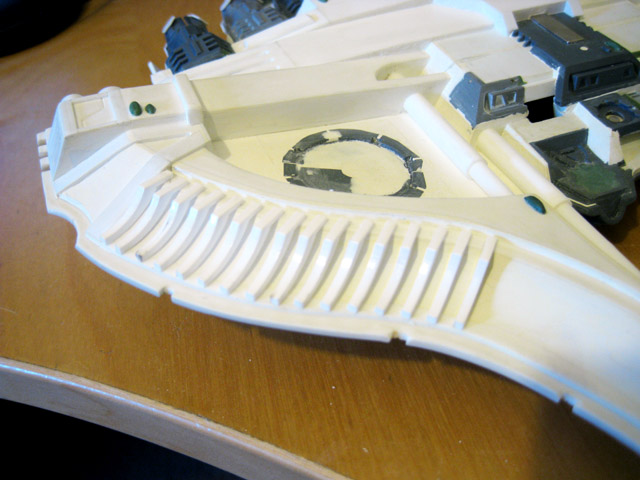
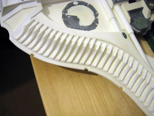
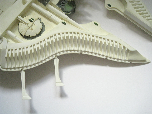
68. The anti-grav vanes on the forward prongs start to take shape.
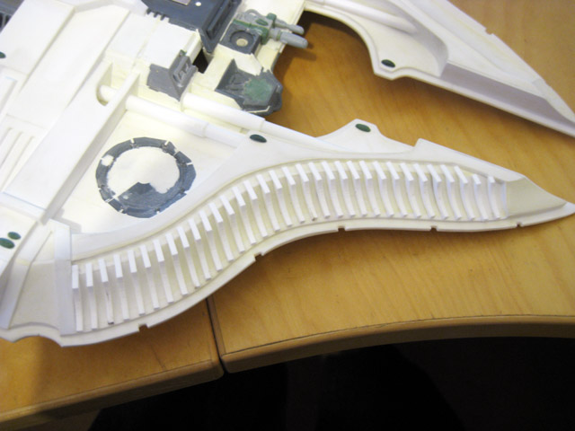
69. The port-side prong, with 33 vanes glued in place. Some gap-filling work with Milliput will be needed to blend them in properly with the rest of the hull, but even at this stage I was delighted with the effect.
70. Both prongs completed.
71. Work begins on filling in the gaps and blending in the vanes with the hull.
72. Some further conversion work on the generator in the upper hull.
73. The first of four "Wave Serpent"-style force-field projectors on the upper hull.
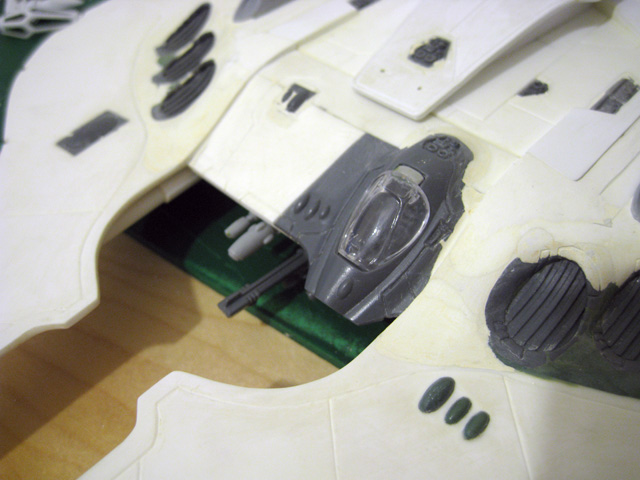
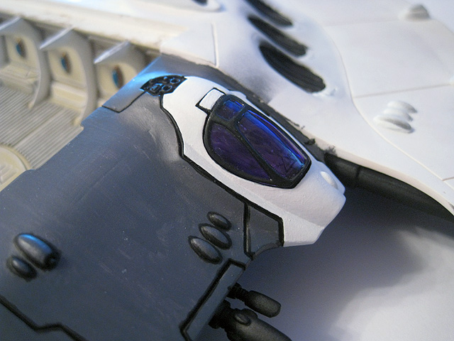
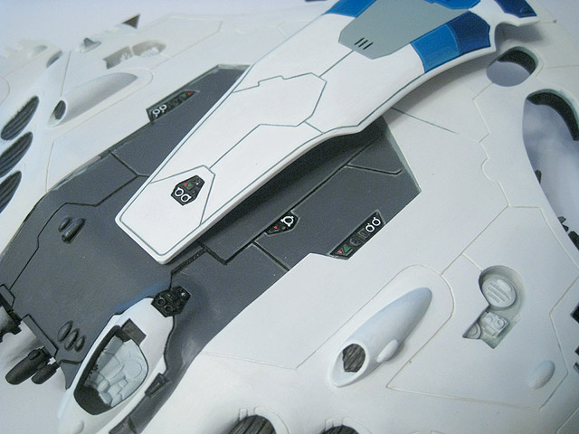
74. A close-up of the cockpit.
75. An updated rear view of the Pegasus.
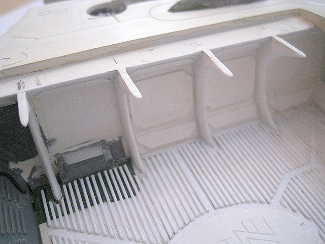
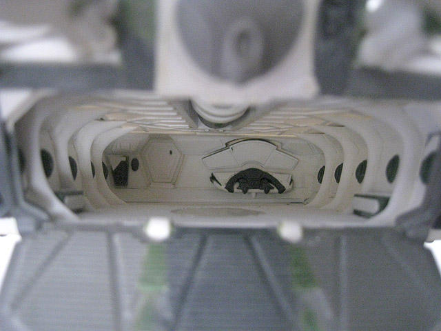
76. A view of the interior.
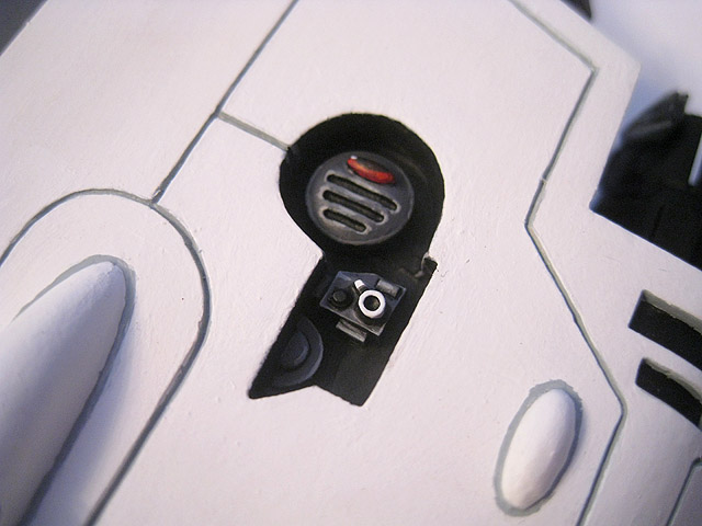
77. I updated the sensor array so that it better blends in with the rest of the hull.
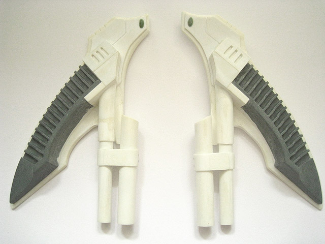
78. The fins are now virtually complete.
79. The force field projectors take shape.
This is one of two missile launchers, modelled using the end of a plastic Eldar Missile Launcher from the heavy weapons sprue.
This represents one of the two electromagnetic pulse emitters.
80. More detail has been added to the underside.
81. An updated underside view of the Pegasus. Most of the remaining work on the exterior comes down to gap-filling and tidying up (and finishing the two remaining force field emitters).
82. Another view of the upper hull. The starboard side still needs some work and some panel lines need to be finished, but most of the detail has been completed now. The interior is the single biggest area left to complete at this point.

83. With the exterior design virtually complete at this stage, I created this technical line drawing of the Pegasus in Adobe Illustrator, in the style of the diagrams seen in the Forge World Imperial Armour books.
84. The completed fins.
85. Underside of the completed fins.
86. Completed upper hull force field projectors.
87. Completed detail on the starboard engine cluster.
88. The anti-grav vanes on the underside of the portside forward prong are now completely finished, after much gap-filling with White Milliput.
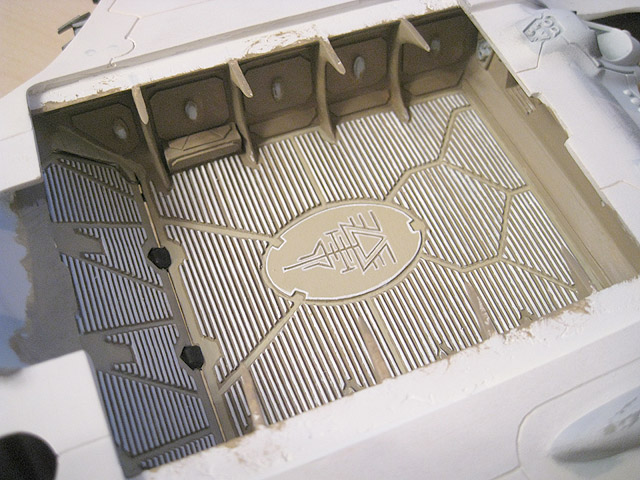
89. The ceiling of the hold has been updated with some raised design work.
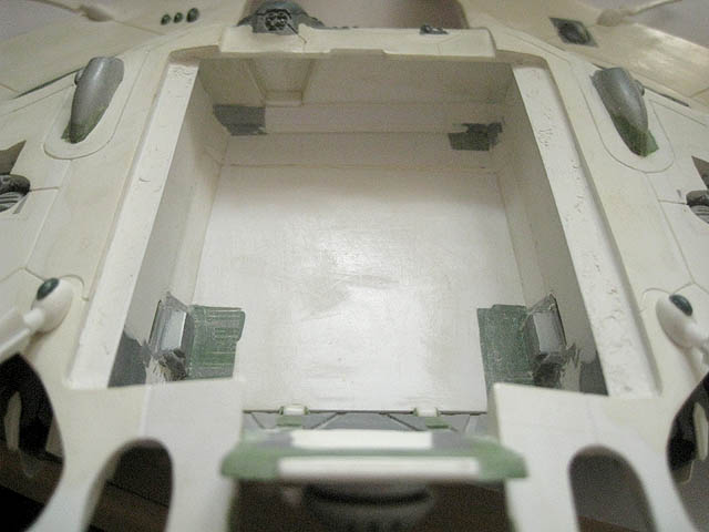
90. An updated shot of the Pegasus's interior space. Gaps have been filled and it is now ready for detail to be added. Once the interior and the (currently) removable upper hull have been painted, the upper hull will be glued on so that I can blend it in with the main body of the Pegasus. I toyed with the idea of leaving it removable, but the gap around the edge distracts from the design and spoils some of the lines.
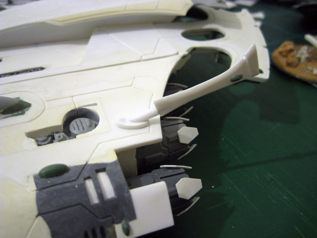
91. I decided to change the weapon mount under the cockpit, replacing the standard Falcon weapon mount for something akin to the secondary weapon mount on the Lynx. It can now accept several different magnetised weapons.
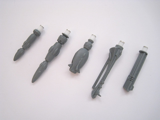
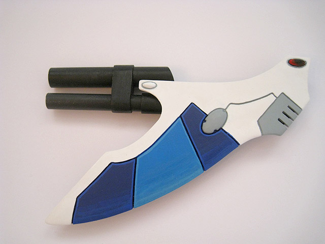
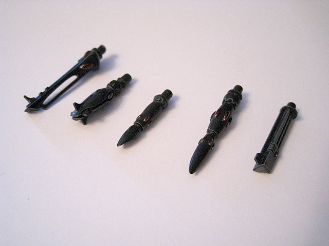
92. These are the magnetised weapon options for the Pegasus. From left-to-right; Bright Lance, Pulse Laser, Starcannon, Shuriken Cannon and Scatter Laser (the Eldar Missile Launcher has been omitted as the Pegasus has two of those already). This style of magnetised weapon is compatible with my Lynx and Crimson Hunter.
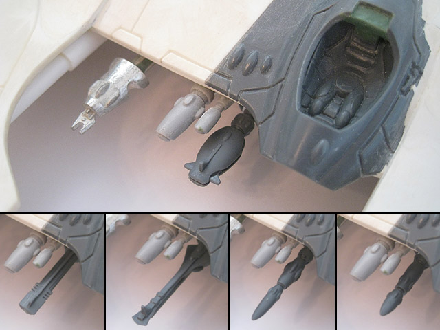
93. Some close-ups showing the different weapon options in situ.
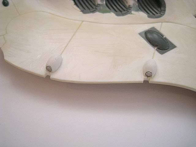
94. After breaking one of the fragile force-field projectors on the forward prongs (and not for the first time) I decided to magnetise them all instead.
95. The magnetised force-field projectors.
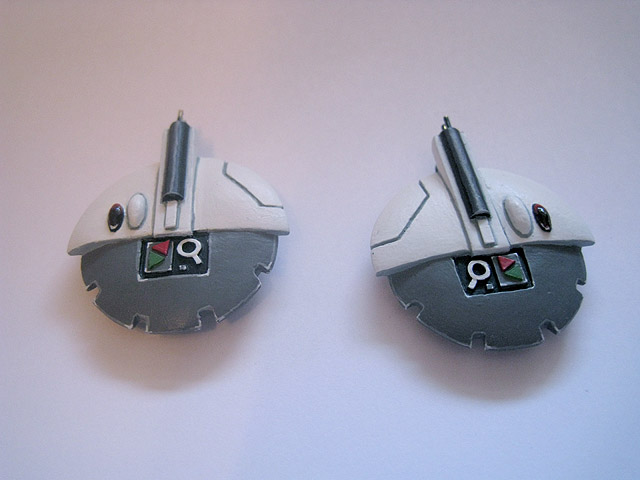
96. An electromagnetic pulse wave is emitted from these generators under the hull. The detail work on these has now been completed and they will be painted separately before being glued in place.
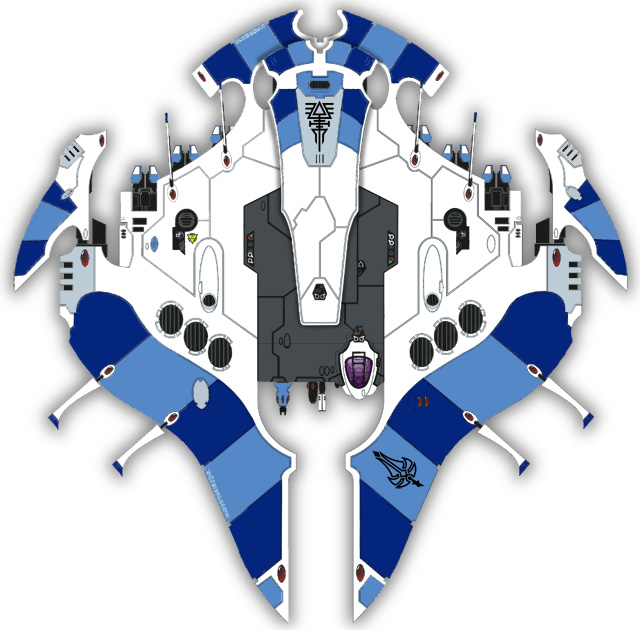
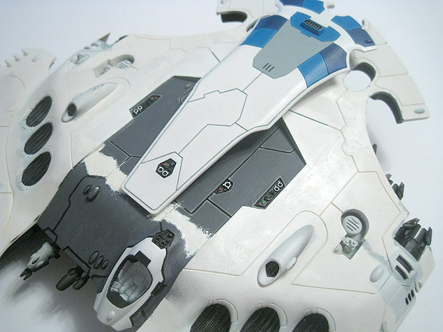
97. After much deliberation, I have settled on this design as the colour scheme for the Pegasus (though the final design may differ slightly once I see how it looks on the model). The central area is a dark grey, which echoes the dark mid-section of the unnamed vehicle in the original artwork that inspired the project (seen at the top of the page).
98. An important milestone - the first component to be painted.
99. Underside of the (mostly) completed fin.
100. An updated work-in-progess shot of the Pegasus. All of the detail on the upper hull is now finished. The interior and underside are nearly complete at this point and work has begun on the scenic base(s).

101. The rune for the Pegasus. This combines elements of the Falcon, Wave Serpent and Swooping Hawk runes.
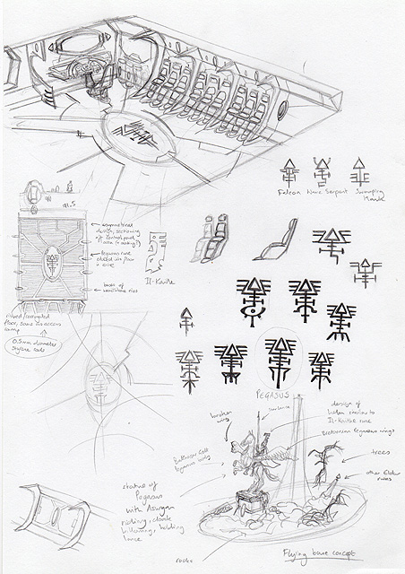
102. I drew some rough concepts for the interior and the flying base. This also shows various alternatives for the Pegasus rune before I settled on the final design.
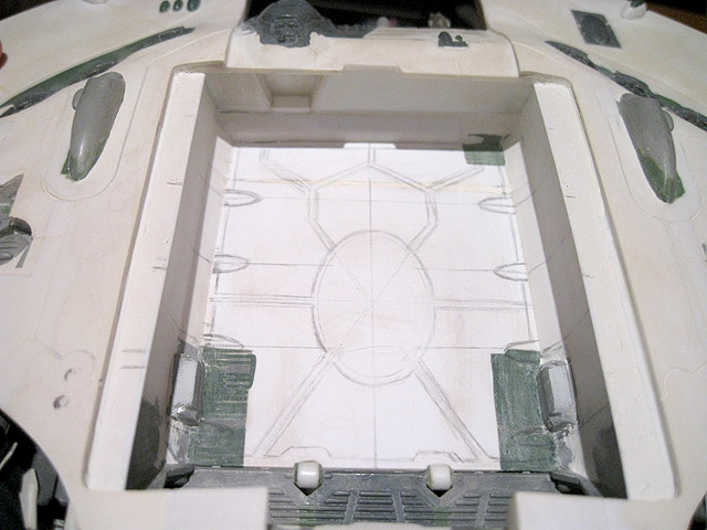
103. I sketched out the design for the floor using pencil.
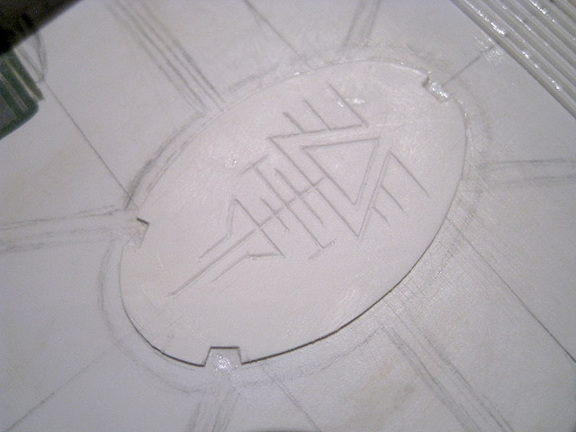
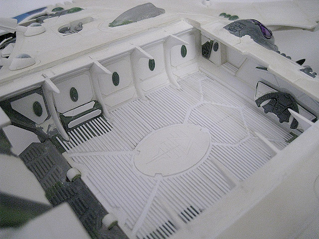
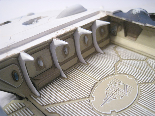
104. The centrepiece of the floor design is this oval section featuring the rune for the Pegasus, which I etched into the plasticard.

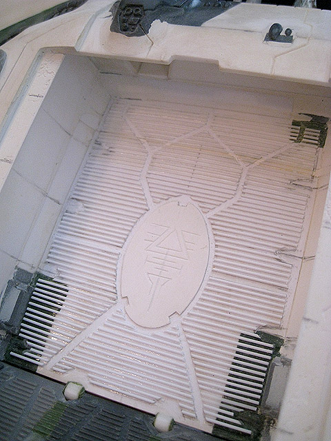
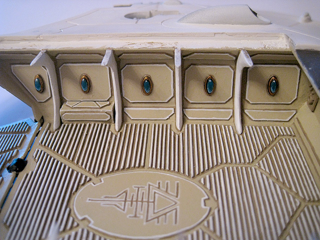
105. The completed floor. The ribbed sections echo the design of the access ramp - I wanted that design to carry through.
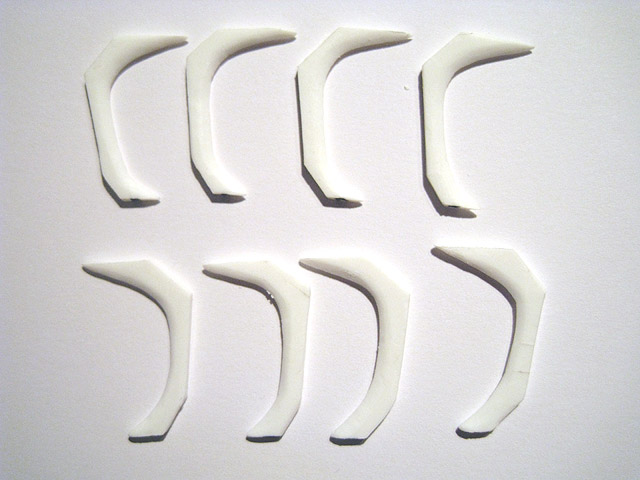
106. These are the wraithbone ribs for the interior of the Pegasus. Eldar craft are constructed around a skeletal frame of psychically-grown wraithbone and are often described as having rib-like protruberances running along their length. These were cut from plasticard that was then filed and sanded down. They will be glued in the interior.
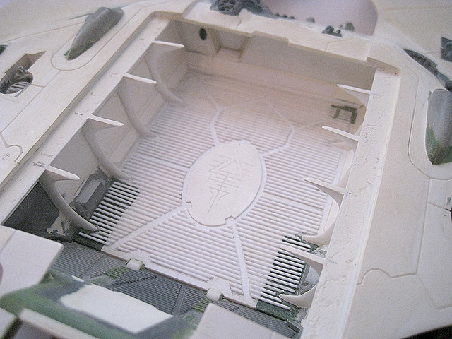
107. The interior continues to take shape and the wraithbone ribs have now been glued in place.
108. A close-up shot of the wraithbone ribs on one side of the interior.
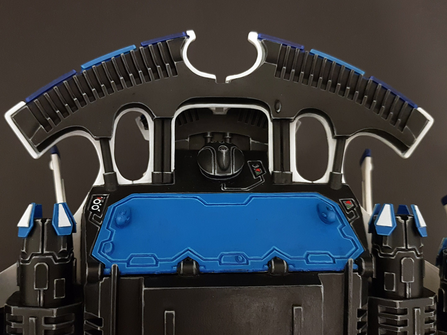
109. A shot of the completed interior roof. Some minor changes were made to the decorative elements to accommodate the wraithbone ribs.
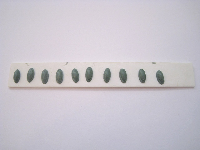
110. These gems were made from Green Stuff, using a mould to make them (fairly) uniform in appearance.
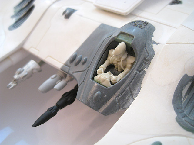
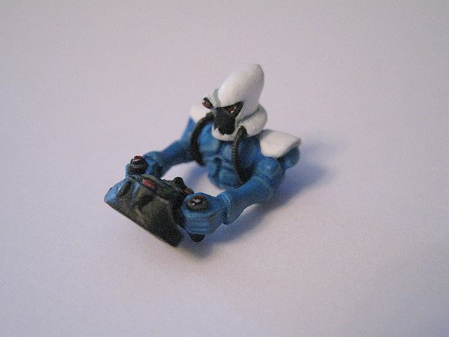
111. A close-up of the pilot. This design of pilot comes with the Forge World Eldar Lynx & Hornet models and I much prefer it to the older designs from the Falcon kit.
112. The starboard anti-grav vanes have finally been finished and are now blended in properly.
113. A close-up of the finalised underside detail.
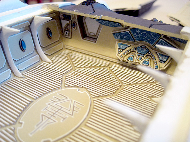
114. The completed interior.
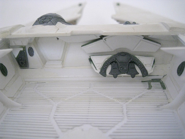
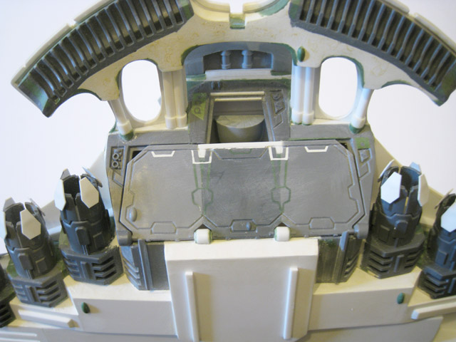
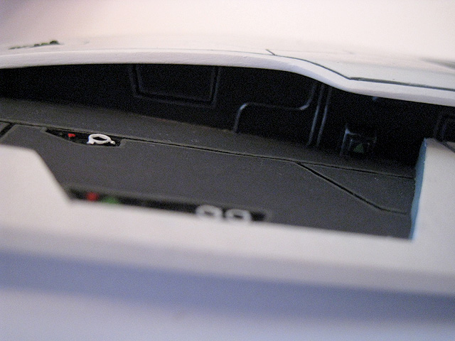
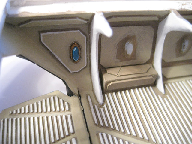
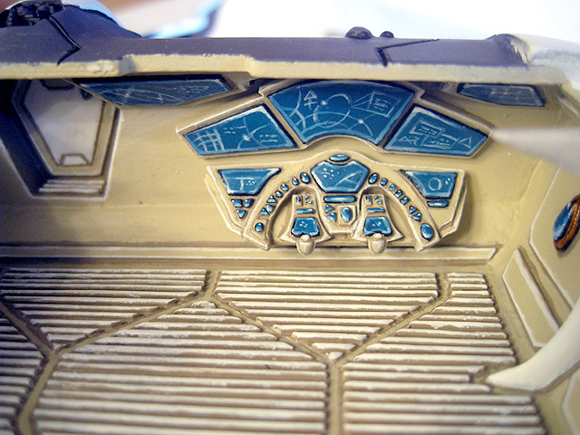
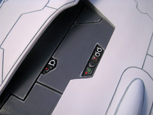
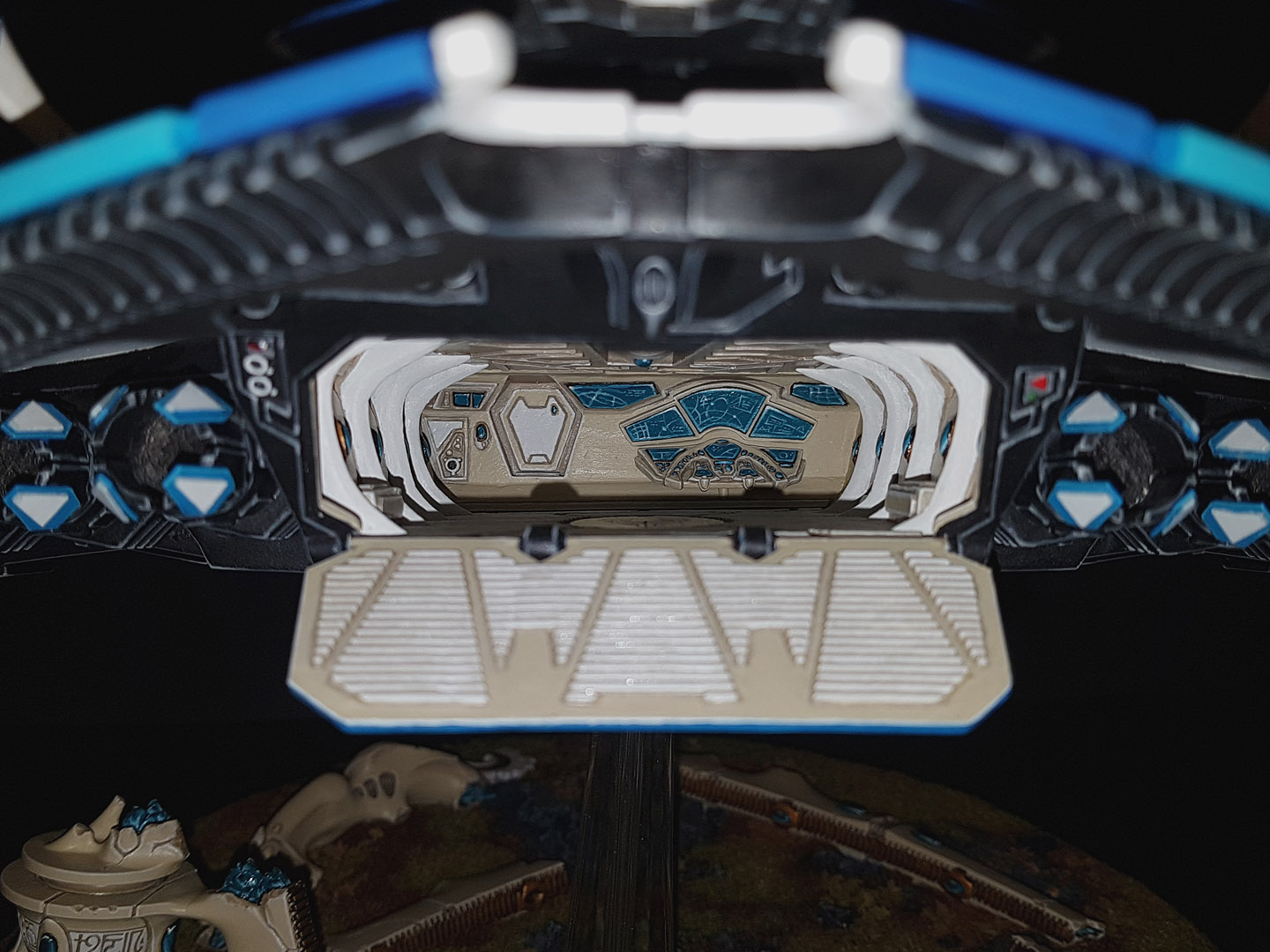
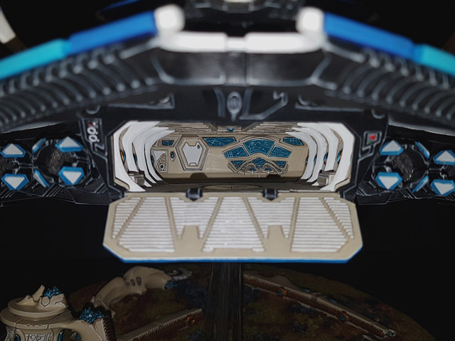
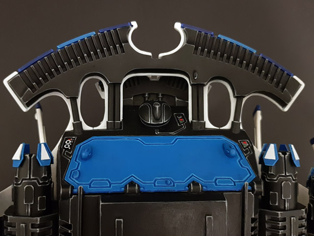
115. A close-up shot of the back wall of the interior, featuring the access hatch into the cockpit and a command station with various controls and screens.
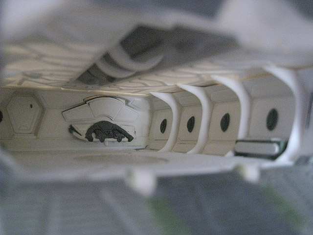
116. A view of the enclosed interior.
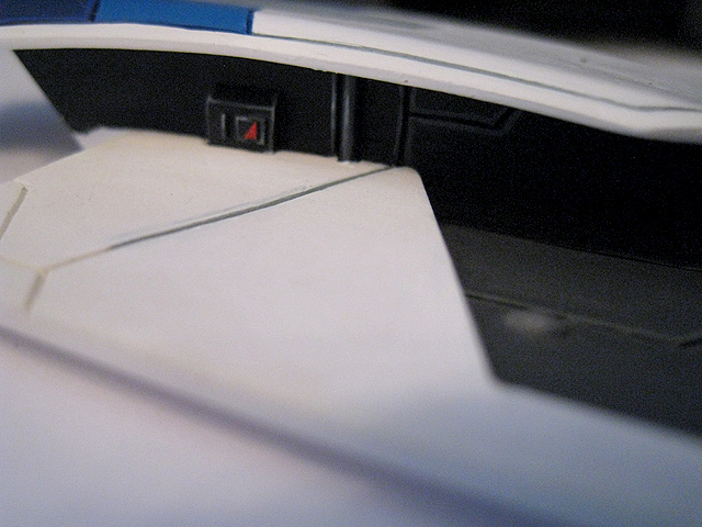
117. A different view of the interior, with the roof in place. The interior and the underside of the roof will be painted before the roof is glued in place and blended into the outer hull.
118. Construction of the Pegasus was completed on 11th June 2015 - over 4 years since I started it in January 2011.
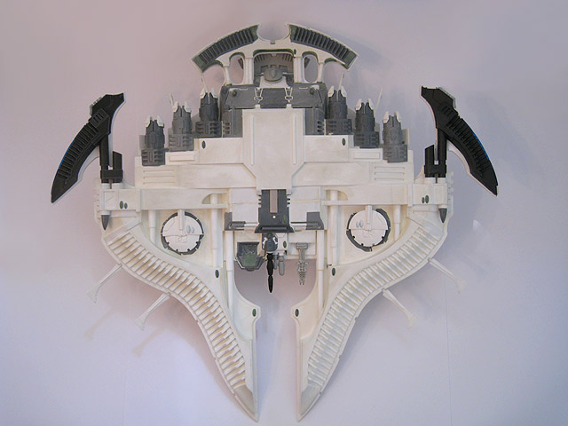
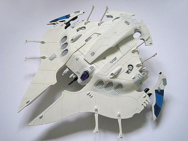
119. An underside view of the fully-assembled Pegasus.
120. Rear elevation of the Pegasus.
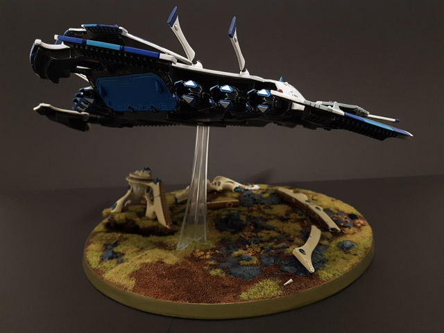
121. A rear view of the completed Pegasus. Although it is large, it is still very low and wide, which I think helps to preserve the Eldar aesthetic and not make it appear too bulky or ungainly.
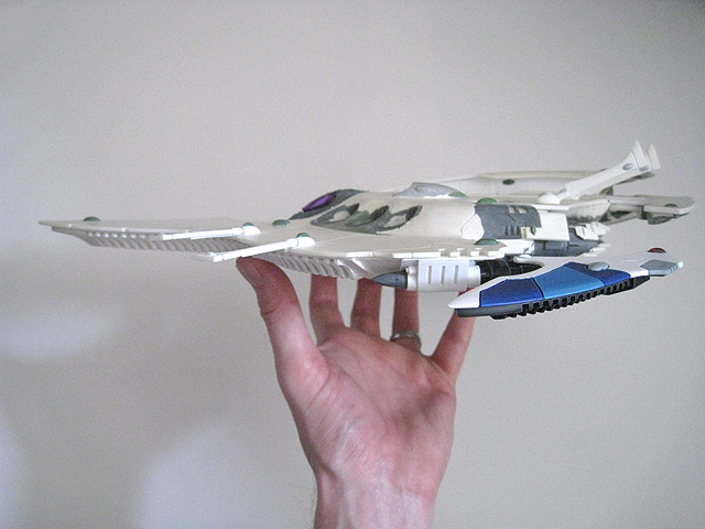
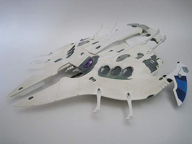
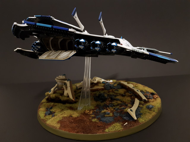
122. A side view of the assembled Pegasus. The silhouette is quite typical of Eldar tank designs but I think it still looks quite distinctive.
123. The Pegasus has now been undercoated and is ready to be painted in its entirety.
124. A work-in-progress shot of the upper hull, partway through painting.
125. A close-up of some of the detail under the curved upper hull.
126. Close-up of some more detailing.
127. The magnetised weapon options are all painted. Some of these can also be used on the Lynx and Crimson Hunter.
128. The pilot, now painted.
129. The four force field projectors for the upper hull are now all painted.
130. A close-up of the underside of the rear fin on the upper hull.
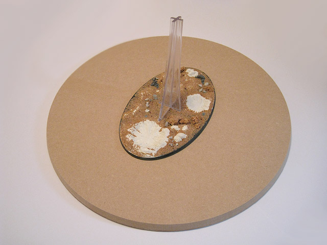
131. After some deliberation, I decided to have a large (320mm diameter) MDF base specially made for the Pegasus. This is substantially larger than the work-in-progress oval flying base and will allow me to add more scenic elements.
132. Both of the fins are now completely painted and varnished.
133. The underside of the fins.
134. The underside of the upper hull forms the roof of the Pegasus' interior. This has now been painted and varnished and is ready to be glued in place, once the interior has been painted.
135. Work has now begun on painting the interior.
136. The textured floor and access ramp are now virtually finished.
137. The wraithbone ribs have now been painted white.
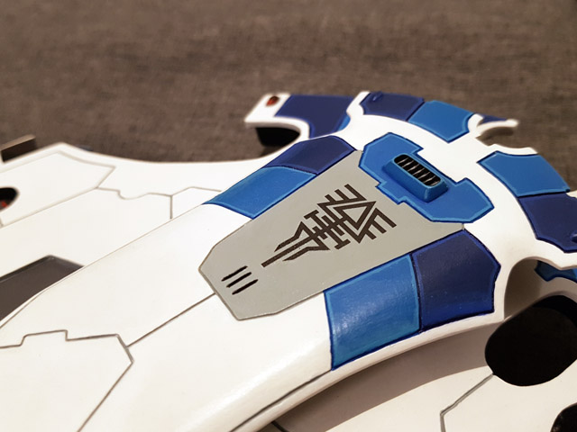
138. The first section of panelling has been completed - this colour scheme will be repeated on the other panels.
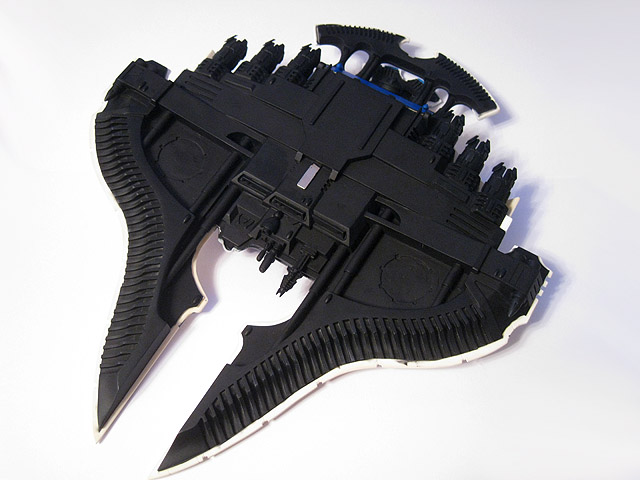
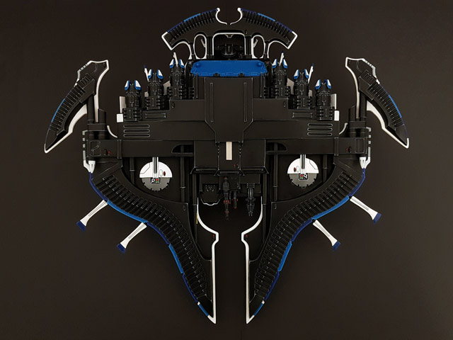
139. The underside has been undercoated black. I masked off the rest of the model and used a spray undercoat, though a brush will be needed to fill in some gaps.
140. The central section has been basecoated, which gives more of an impression of what the final paint scheme will look like.
141. A close-up of the central section of the Pegasus. As the interior is not yet complete, the upper hull has not been glued in place at this stage.
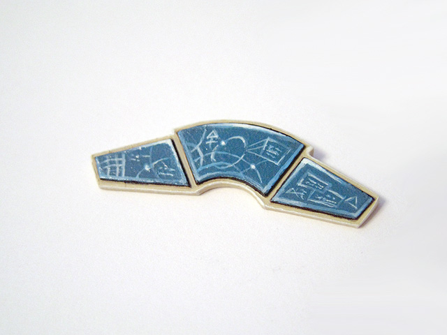
142. These screens were painted freehand and will be attached to the rear wall of the interior.
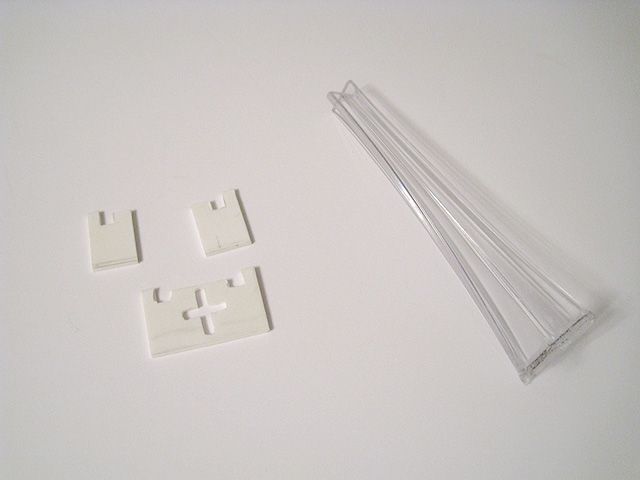
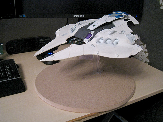
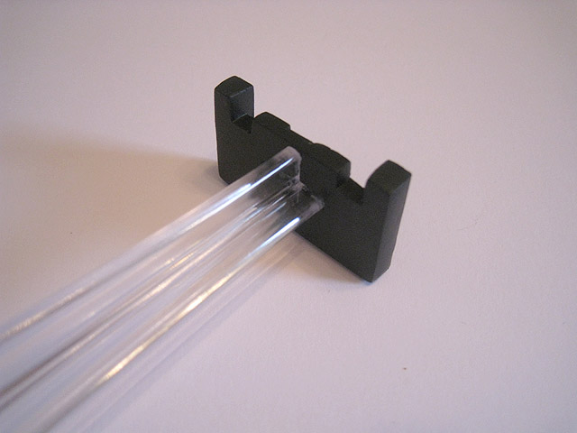
143. The Pegasus will be supported on its base with a custom-made plasticard support and a modified flying stem (cut at an angle, to make the Pegasus appear to be swooping down).
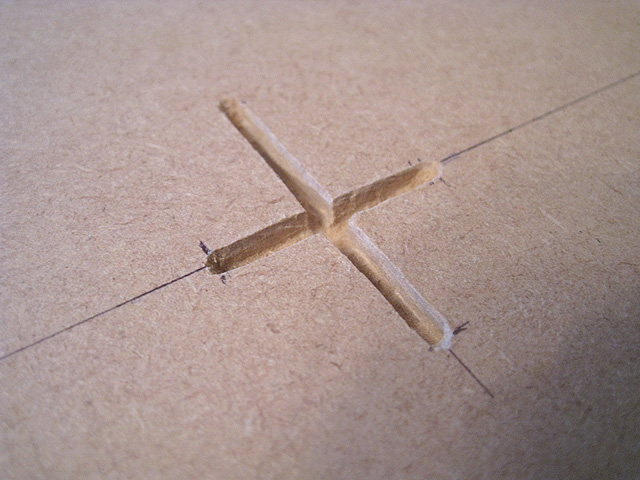
144. In order to securely attach the transparent flying stem to the scenic base, I carefully drilled out a recess in the MDF base.
145. A dry-fit of the components of the flying stem.
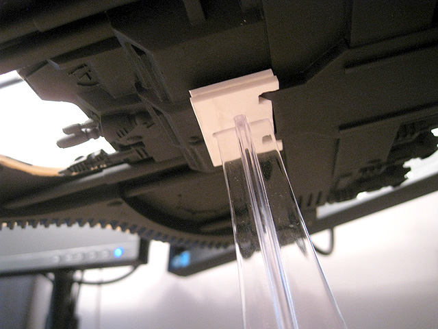
146. A view of the underside of the Pegasus where it connects with the stem.
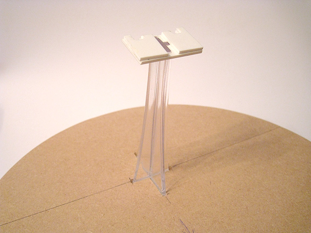
147. It's very important that the Pegasus is stable on its base - in this photo, none of the elements of the base or flying stem have been glued together and there are no magnets being used either. The Pegasus is completely supported by the flying stem as the components fit so tightly together that glue isn't needed (but will of course be added later!).
148. A mock-up of the scenic elements of the base. I decided to use one half of a ruined Webway Gate.
149. A close-up showing the early stages of the exterior painting of the cockpit.
150. The port-side interior wall was the first to be completed.
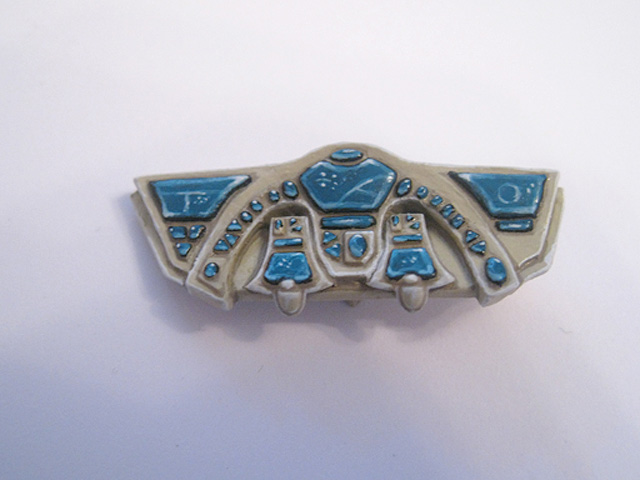
151. The fully painted (and varnished) control panel. Gloss varnish was used to pick out the multitude of gems and display panels.
152. The display screens and control panel have now been glued in place.
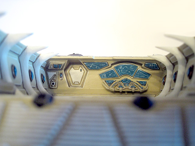
153. Close-up of the fully-painted interior.
154. This shows the completed interior (with the upper hull removed), as viewed from the rear access ramp.
155. With the upper hull finally glued in place, I used White Milliput to fill in the joins.
156. After sanding down the White Milliput, I touched up the areas of damaged paintwork. I am very pleased with how well the parts have blended together as the joins are nearly invisible.
157. A close-up of the painted cockpit, before the pilot's torso was glued in place.
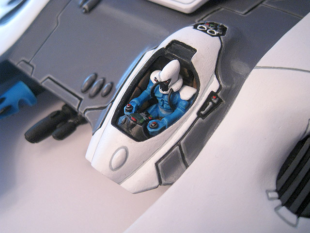
158. The pilot, now glued into position.
159. An updated work-in-progress shot of the painting of the Pegasus. All of the basecoating is virtually complete at this point.
160. In order to make the scenic base appear more natural and irregular, I used some Polyfilla to build up some areas.
161. The scenic base features half of a ruined webway gate, which has been shattered into multiple pieces. The bottom section will appear to be uprooted (like a falling tree).
162. The underside of the webway gate was built up using more Polyfilla.
163. This close-up shows how the bottom section of the webway gate will sit on the base.
164. The magnetic flying stem is now complete.
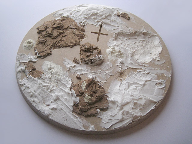
165. The base, after the Polyfilla had been sanded to remove irregularities.
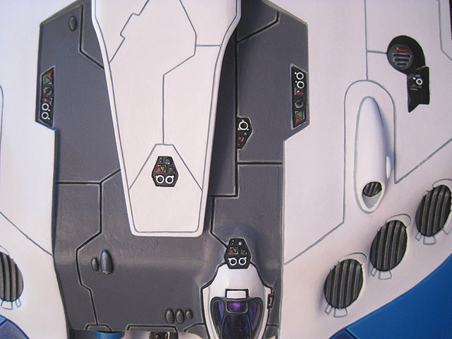
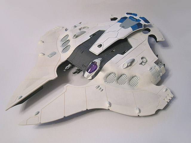
166. A close-up of the upper hull of the Pegasus, which is nearly completed now.
167. Close-up of some detailing on the upper-hull. This was made using part of a Phantom titan D-cannon.
168. Another close-up of some more detail on the upper hull.
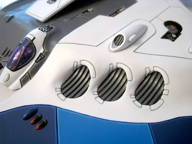
169. The triple engine intakes are completely painted now.
170. A close-up of the underside of the Pegasus, showing the work-in-progress of the painting.
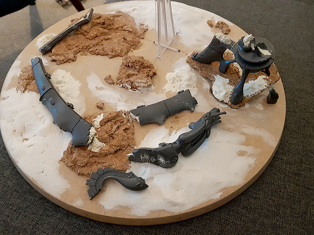
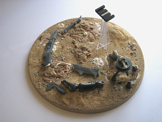
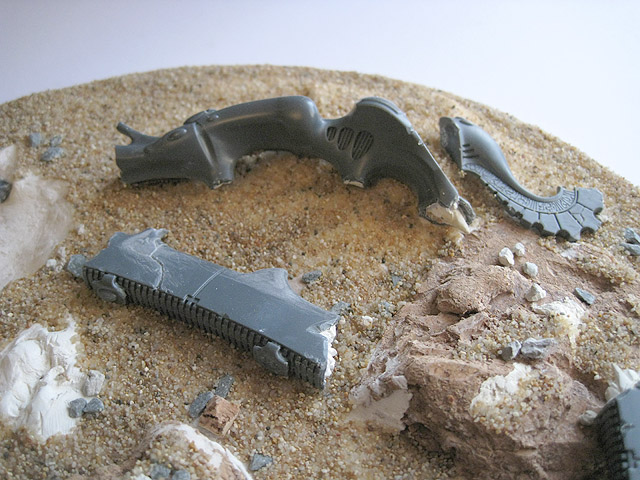
171. This mock-up of the base shows how the fragmented components of the ruined webway gate will be arranged.
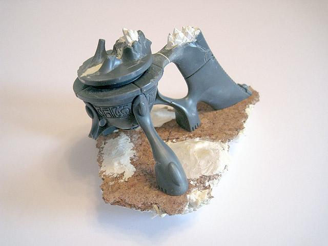
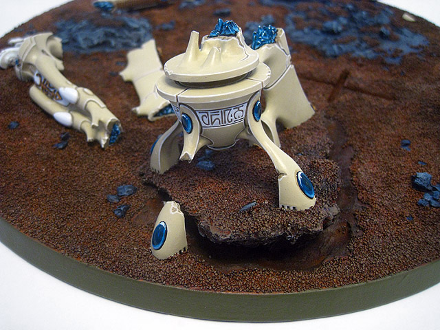
172. A close-up of the ruined statue that forms part of the gate.
173. I had some custom transfers printed, including this large one for the upper hull of the Pegasus.
174. The forcefield generators, now painted.
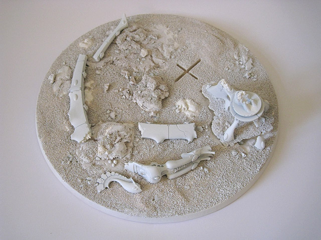
175. The scenic base has now been fully assembled and is ready to be undercoated.
176. A close-up of the ruined statue from the destroyed webway gate.
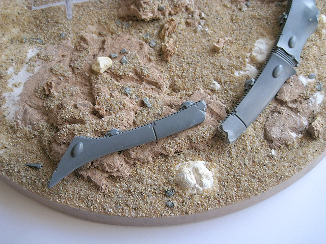
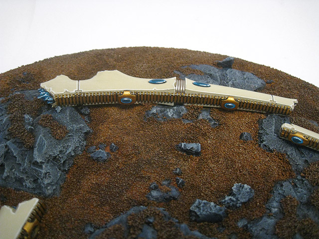
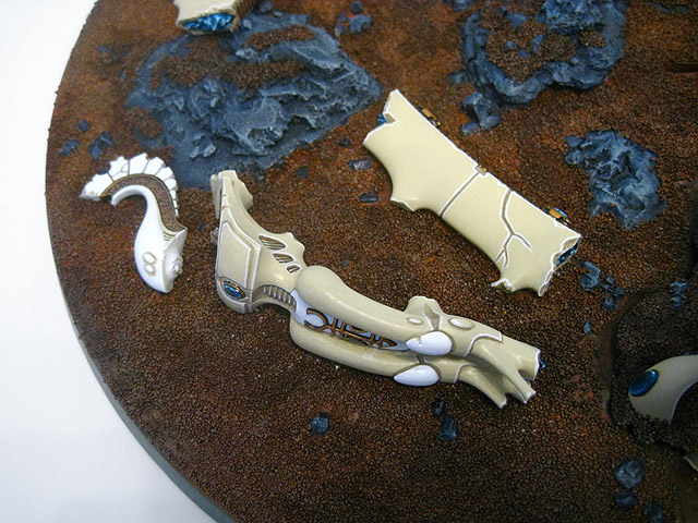
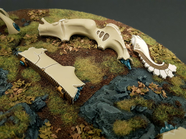
177. The gate itself has fractured into several pieces. The very tip has been chipped off and can be seen on the ground in the left of the photo.
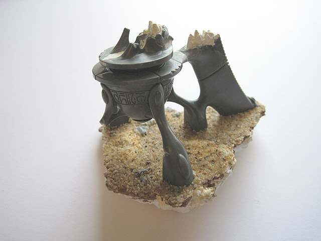
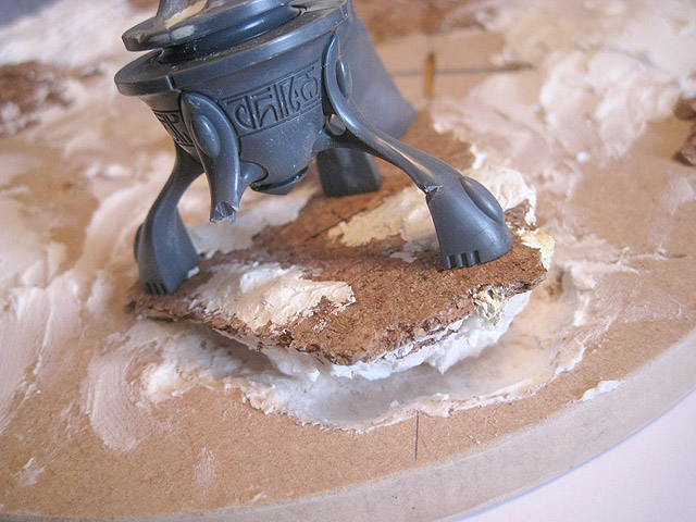
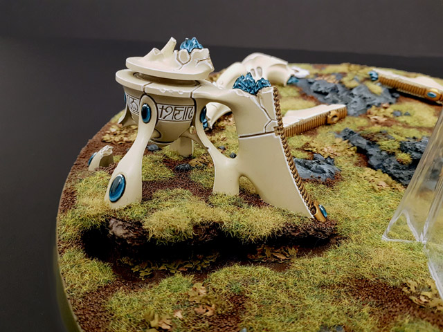
178. The pedestal for the ruined webway gate has been kept separate for ease of painting. It has been modelled on a tilted section of uprooted earth, to give the impression that the gate suffered a massive impact, causing it to fall and shatter. The base of the gate tore up the earth in the process, uprooted like a tree.
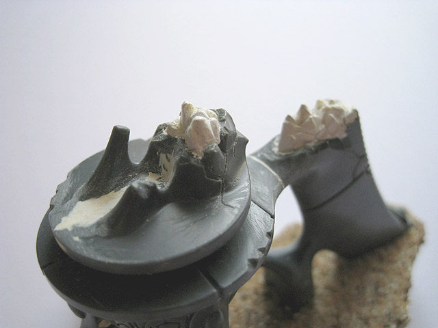
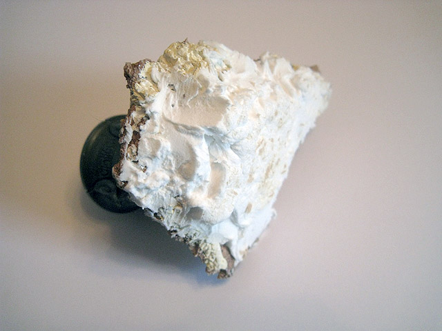
179. I used White Milliput to sculpt cracked crystalline structures where the pieces of the gate had separated. I envisage these as being the crystal core of the gate; rather than having internal circuitry or mechanical workings, this seemed to fit the Eldar better.
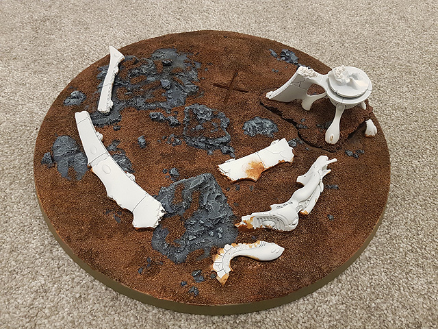
180. The base has been undercoated and the completion of the project is finally in sight.
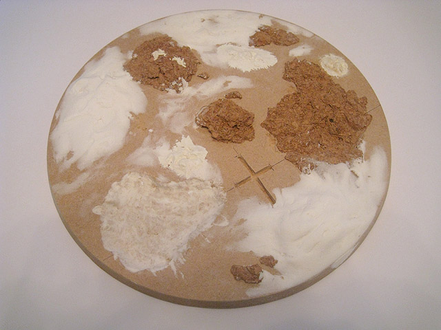
181. A work-in-progress shot of the painting of the scenic base. Various washes in different combinations and concentrations were used to produce variations in the ground/dirt.
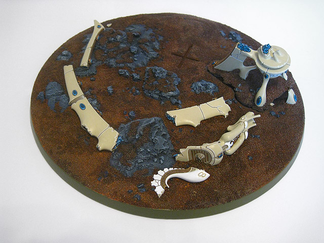
182. The base has now been fully painted and varnished, it just needs some static grass adding.
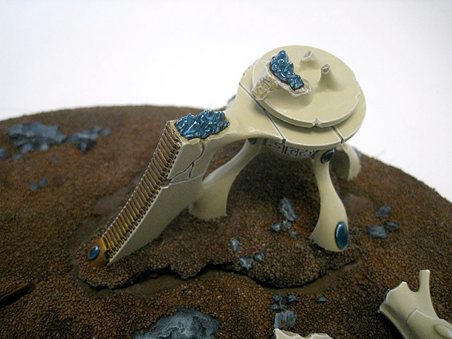
183. A close-up view of the base of the ruined webway gate. The protruding shattered crystals can be seen clearly - I had been worried about painting these but they turned out better than I'd expected.
184. Alternate view of the base of the webway gate.
185. Part of the ruined webway gate. I intend to use the same colour scheme when I assemble my intact gate as well.
186. The fallen statue from the webway gate.
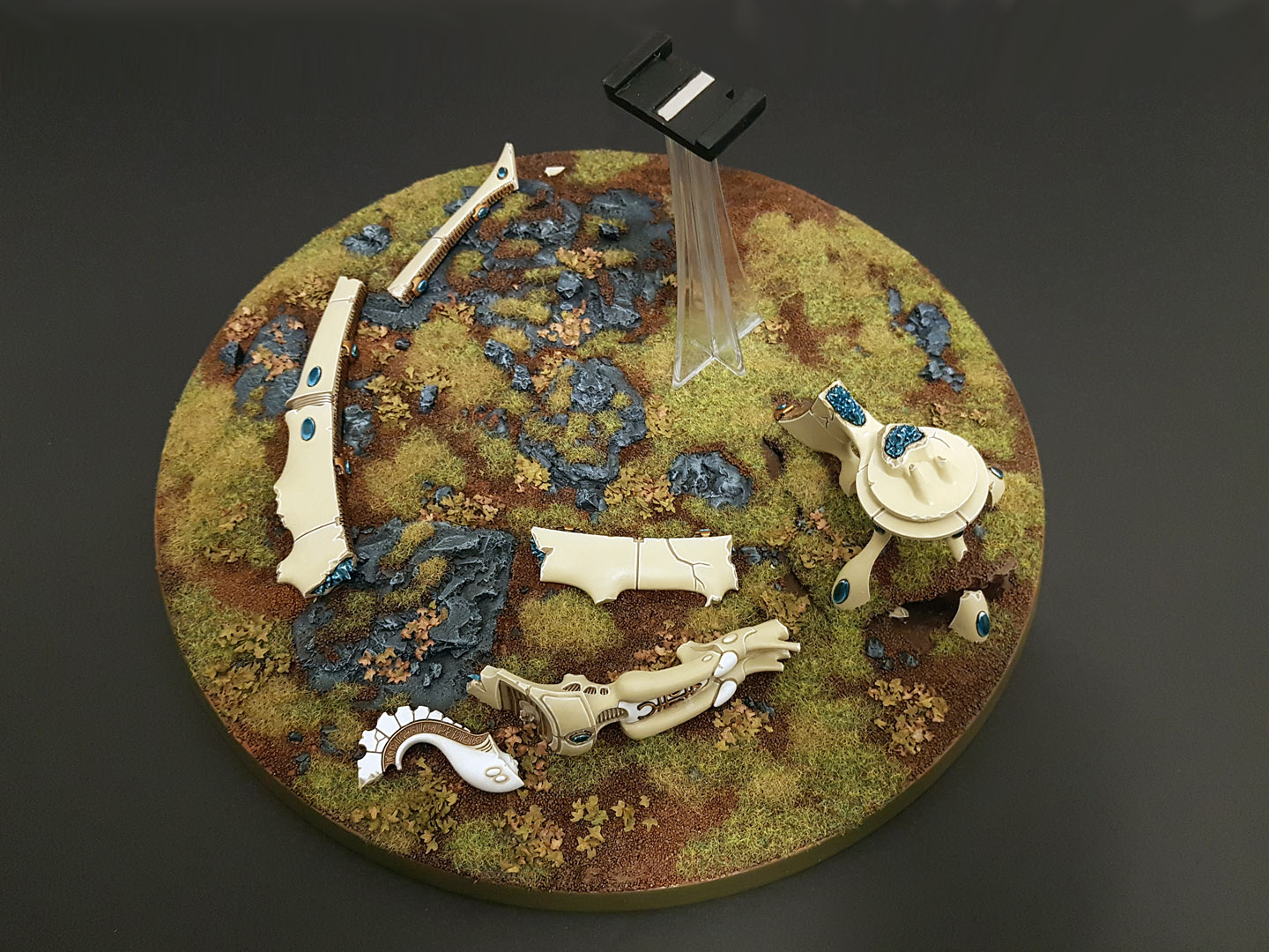
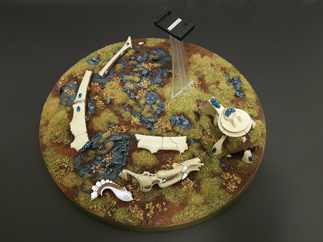
187. The completed scenic base. I used two varieties of static grass to produce some natural variation, as well as two varieties of leaves to give an autumnal effect.

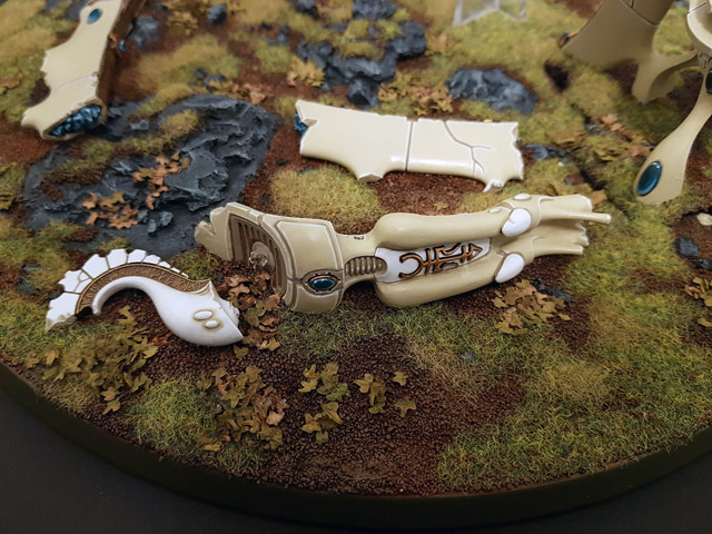
188. A close-up of the ruined webway gate statue.

189. Rear angle of the ruined webway gate statue.

190. Close-up view of the pedestal of the ruined webway gate.

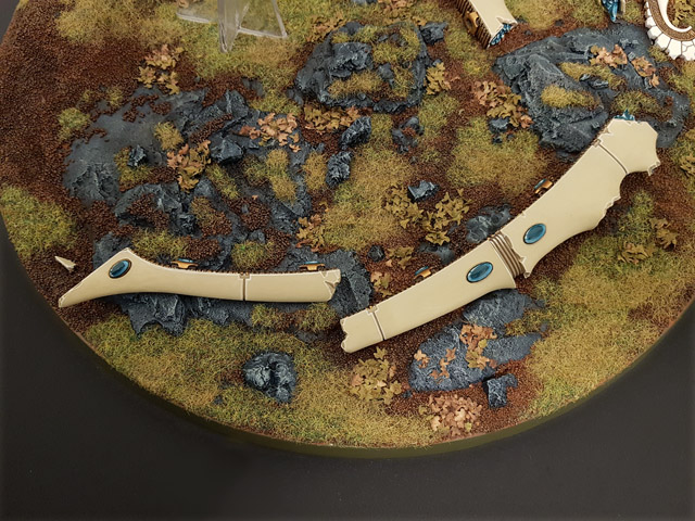
191. Top-down view of the top sections of the fallen gate.
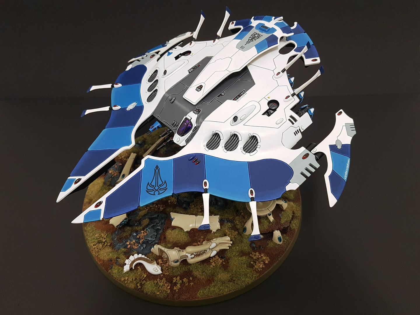

192. After more than 9 years from the start of the project; the fully painted and completed Pegasus.

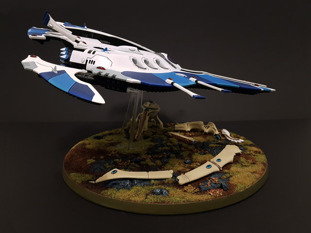
193. Starboard view of the Pegasus.

194. Rear elevation of the Pegasus.

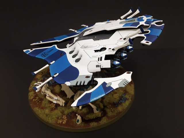
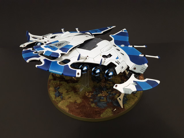
195. Another angle of the completed model.

196. Rear view of the Pegasus.

197. Rear view with the access ramp open.
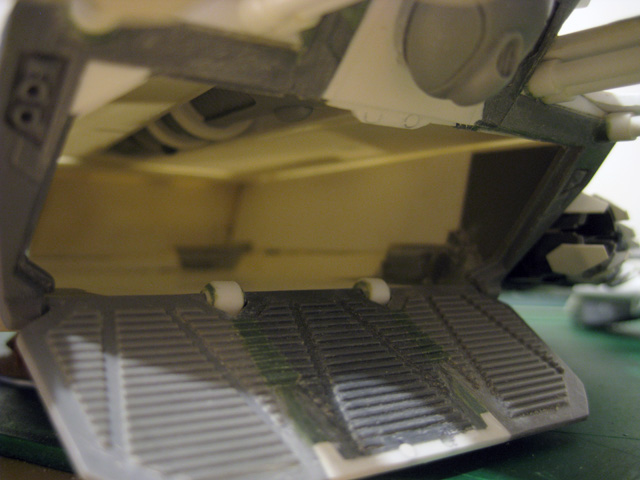
198. A view of the interior through the open access ramp.

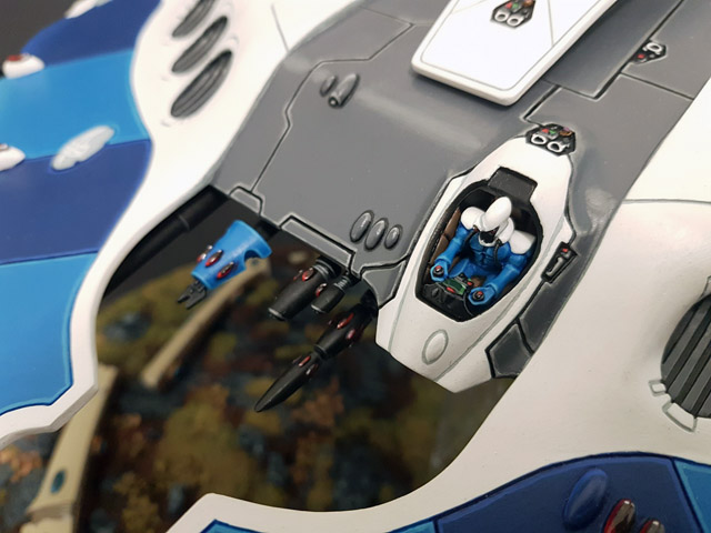
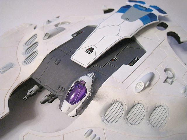
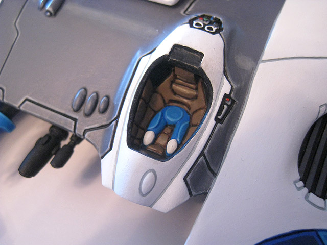
199. A close-up of the pilot and cockpit, with the magnetic canopy removed.

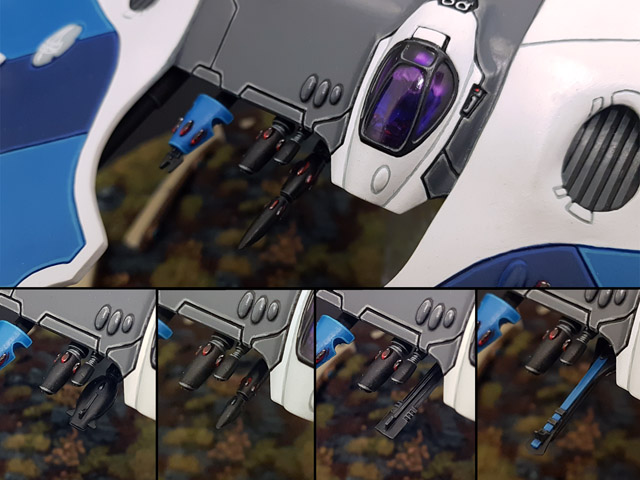
200. The various weapon options for the mounting point under the cockpit.
201. Underside close-up of the rear fin and access ramp.
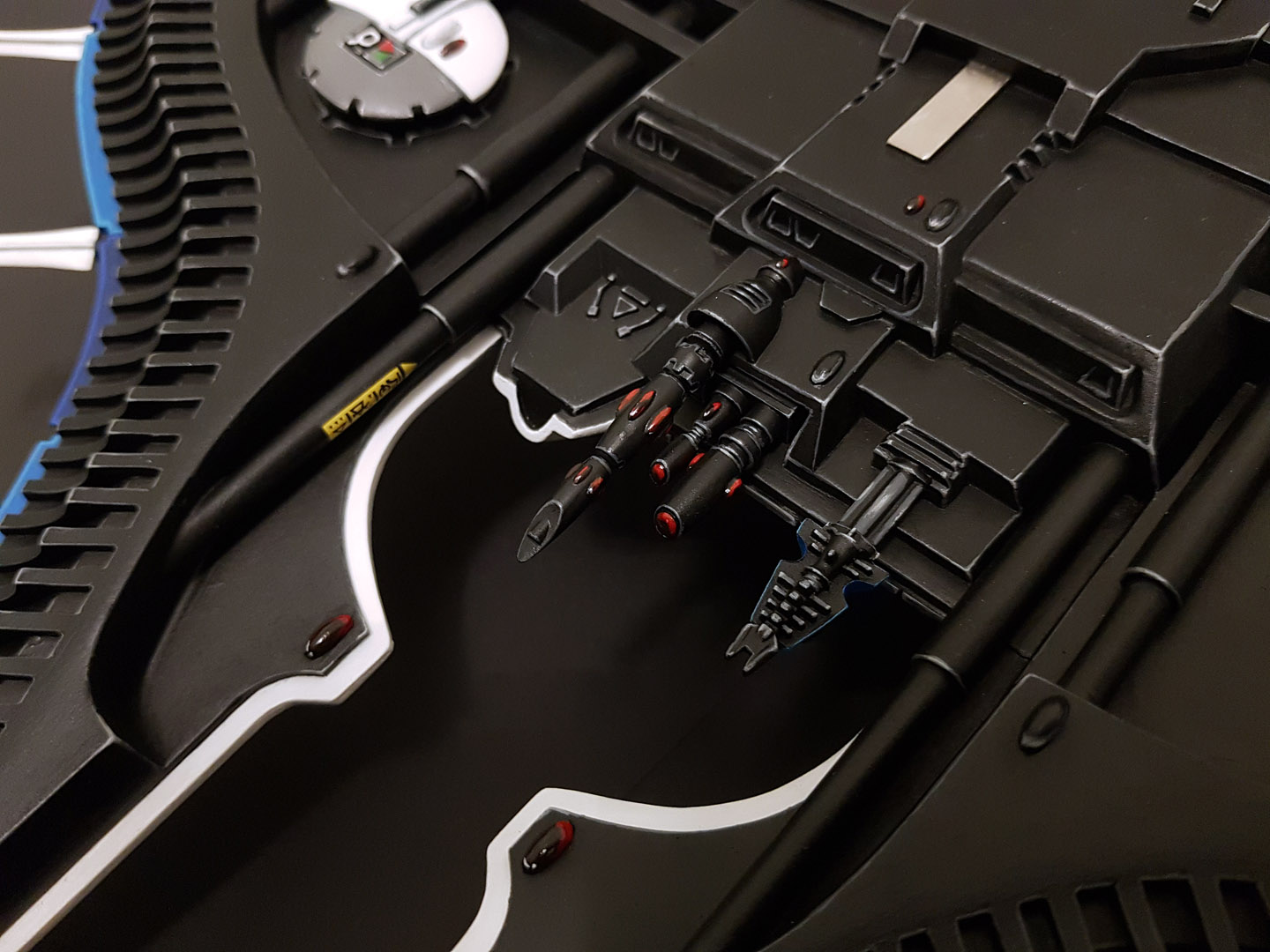
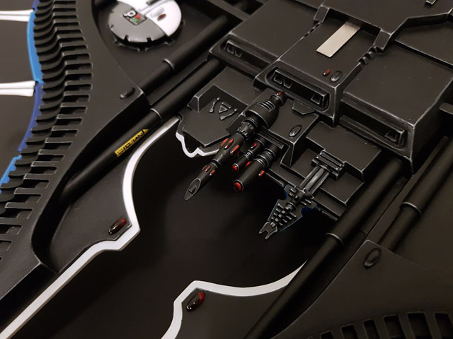
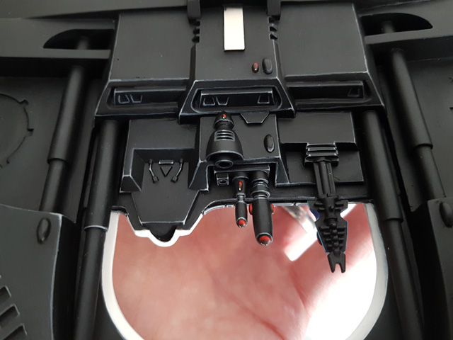
202. The underside of the cockpit, with the weapon mount and sensor arrays.
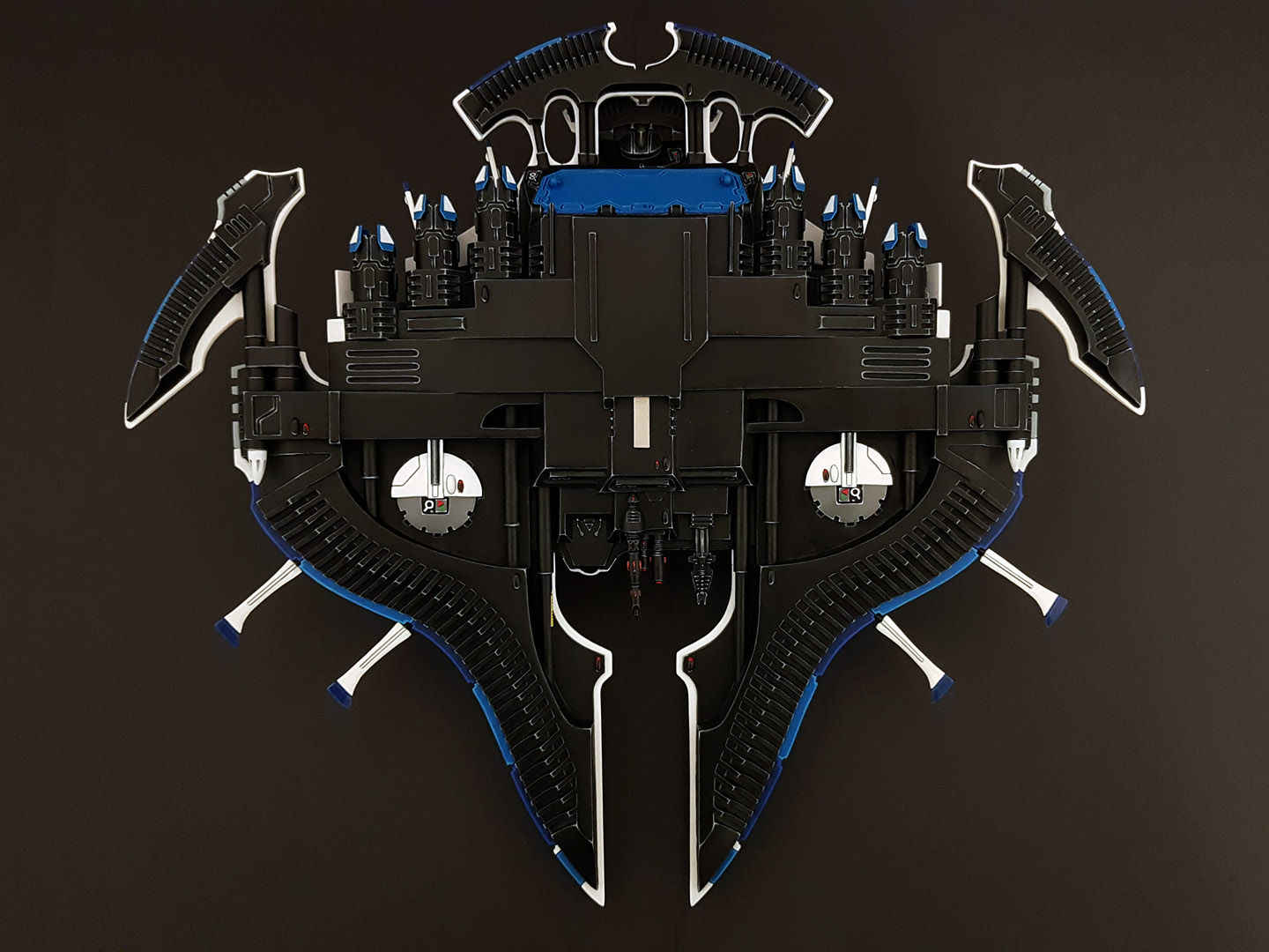
203. Underside view of the completed model.
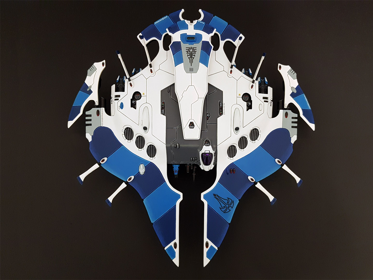

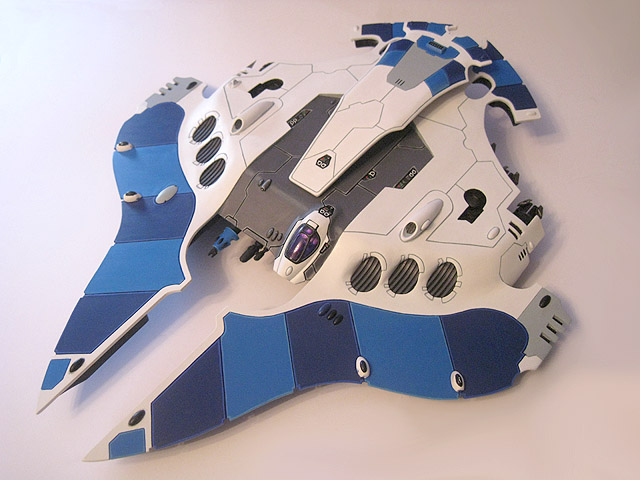
204. Dorsal view of the completed Pegasus. I hope that you have enjoyed following the progress of this project; I never imagined that it would take this long to finish, or that the end result would be half as detailed or complicated as I originally envisaged. I am extremely proud of what I have achieved with this model and it makes the perfect centrepiece for my collection.
comments powered by Disqus